Projection-type image display

a projection-type, image-based technology, applied in the direction of instruments, television systems, optical elements, etc., can solve the problems of high-brightness screen image becoming invisible, load to resolution, and intensity increase,

Inactive Publication Date: 2005-01-06
FUJI PHOTO OPTICAL CO LTD
View PDF1 Cites 29 Cited by
  • Summary
  • Abstract
  • Description
  • Claims
  • Application Information

AI Technical Summary

Benefits of technology

[0011] In order to achieve the above and other objects, the projection-type image display according to the present invention comprises an illumination optical system, an image-light producing device and a projection optical system. The illumination optical system forms an illumination light. The image-light producing device optically modulates the illumination light in accordance with a video signal to produce an image light. The projection optical system projects the image light to a screen. The projection-type image display further comprises at least one stop-adjusting mechanism and a controller. The stop-adjusting mechanism is placed at a predetermined position of an optical path at which the illumination optical system and the projection optical system are disposed, to change an effective luminous-flux diameter at the predetermined position. The controller controls the stop-adjusting mechanism in accordance with a brightness level of the video signal.
[0012] It is preferable that the stop-adjusting mechanism consecutively changes a size of the effective luminous-flux diameter.

Problems solved by technology

These projection-type image displays have a problem in that it is necessary to heighten intensity of a projection image in order to obtain a more visible screen image.
This problem is on the load to resolution in virtue of recent technical progress.
Thus, there arises a problem in that the high-brightness screen image becomes invisible in the dark condition.
Thus, there arises a problem in that some scenes of the screen images are sometimes uncomfortable for watching.

Method used


Image

  • Projection-type image display
  • Projection-type image display
  • Projection-type image display

Examples


Embodiment Construction

)

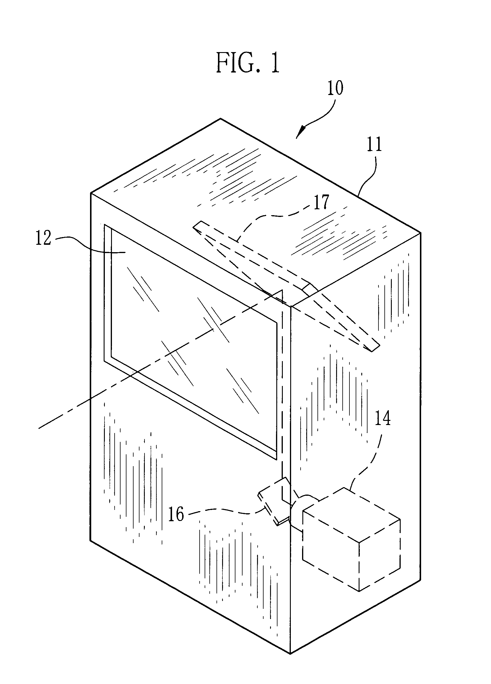
[0020]FIG. 1 shows an external appearance of a projection-type image display 10 provided with a screen 12 of a diffusion transmission type. The screen 12 is disposed at a front face of a housing 11. An image projected to a rear surface of the screen 12 is viewed from a front surface thereof. The housing 11 contains a projection unit 14, a projection image of which is reflected by mirrors 16 and 17 to be formed on the rear surface of the screen 12. It is possible to use the projection-type image display 10 as a large-sized television by driving a liquid crystal element, which is incorporated in the projection unit 14, on the basis of a video signal. In this case, the housing 11 includes a tuner circuit and a well-known circuit unit for reproducing the video signal and a sound signal.

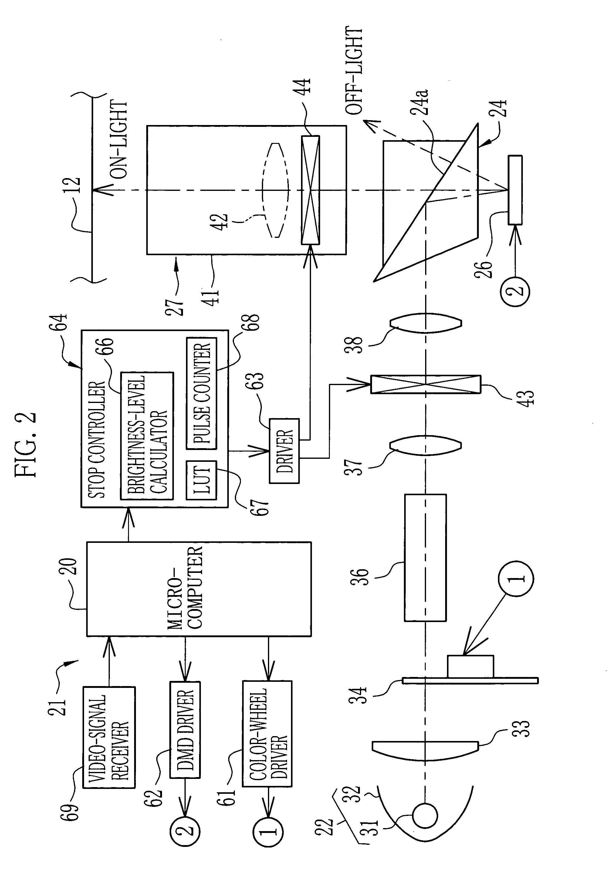
[0021]FIG. 2 schematically shows a structure of the projection unit 14. The projection unit 14 comprises a controller 21 and an optical system. The controller 21 includes a microcomputer 20. The optical...


PUM


Abstract

A projection unit is provided with two stop-changing mechanisms, which are respectively disposed in an illumination optical system and a projection optical system to adjust an effective luminous-flux diameter. A stop controller controls the stop-changing mechanisms in accordance with a brightness level of an inputted video signal to make the effective luminous-flux diameter optimum. This diameter is adjusted so as to be large in a case of a high brightness level, and so as to be small in a case of a low brightness level. When the effective luminous-flux diameter is small, peripheral light of the luminous flux is cut so that contrast becomes high. A screen image is brightly displayed when a picture has the high brightness level, and is displayed in high contrast when the picture has the low brightness level.

Description

BACKGROUND OF THE INVENTION [0001] 1. Field of the Invention [0002] The present invention relates to a projection-type image display of a video projector and so forth comprising an image-light producing device of a liquid-crystal element, a digital micromirror device (hereinafter, called as “DMD”) and so forth. [0003] 2. Description of the Related Art [0004] A projection-type image display in which image light is projected to a screen is known. The image light is produced by receiving and modulating illumination light outputted from an illumination optical system. There are various kinds of the projection-type image displays in accordance with different optical modulation manners. For example, there are a liquid crystal projector and a DMD projector. [0005] The liquid crystal projector comprises a liquid crystal element of a transmission type or a reflection type as an image-light producing section. As well known, the liquid crystal element includes a large number of liquid crystal ...

Claims


Application Information

Patent Timeline
Patent Type & Authority Applications(United States)
IPC IPC(8): G03B21/00G02B27/18G03B21/10G03B21/14G03B21/20H04N5/74
CPCG03B21/10G03B21/2053H04N9/3141H04N5/7416
Inventor KAWAAI, SATORUWATANABE, TAKASHI
Owner FUJI PHOTO OPTICAL CO LTD
Why Eureka
Try Eureka