Channel estimation for block transmissions over time-and frequency-selective wireless fading channels

a channel estimation and block transmission technology, applied in the field of wireless communication systems, can solve the problems of reducing requiring longer sequences of symbols, and reducing the efficiency of the blind channel estimation scheme, so as to maximize the average capacity of the communication channel and minimize the minimum mean-square error (mmse)

Active Publication Date: 2005-01-06
RGT UNIV OF MINNESOTA
View PDF23 Cites 52 Cited by
  • Summary
  • Abstract
  • Description
  • Claims
  • Application Information

AI Technical Summary

Benefits of technology

In general, the invention is directed to techniques for channel estimation of wireless block transmissions over communication channels, which may be both time- and frequency selective fading communication channels. In particular, techniques are described for forming blocks of symbols that utilize blocks of training symbols such that channel estimation is decoupled from symbol detection at the receiver. The structure and coding scheme of the blocks of symbols transmitted over the communication channel are designed and, in one embodiment, minimizes the minimum mean-square error (MMSE) and maximizes the average capacity of the communication channel.

Problems solved by technology

Time- and frequency-selective propagation effects cause performance degradation and constitute the bottleneck for increasing data rates.
Relative to channel estimation schemes relying on training symbols, blind channel estimation schemes typically require longer sequences of symbols and entail higher complexity.
Adaptive or decision directed methods for channel estimation offer reduced complexity alternatives but are prone to error propagation and are limited to slowly varying channels.

Method used


Image

  • Channel estimation for block transmissions over time-and frequency-selective wireless fading channels
  • Channel estimation for block transmissions over time-and frequency-selective wireless fading channels
  • Channel estimation for block transmissions over time-and frequency-selective wireless fading channels

Examples


Embodiment Construction

Throughout the Detailed Description bold upper letters denote matrices, bold lower letters stand for column vectors, (●)T and (●)H denote transpose and Hermitian transpose, respectively; (●)• denotes conjugate and (●)† denotes the matrix pseudoinverse. E[●] stands for expectation with respect to all the random variables with the brackets, ┌●┐ and └●┘ represent the integer floor and integer ceiling, respectively; ★ and † represent convolution and Kroenecker's product, respectively; [A]k,m denotes the (k, m)th entry of a matrix A, tr(A) represents the trace of matrix A, and [x]m denotes the mth entry of the column vector x, and diag[x] stands for a diagonal matrix with x on its main diagonal

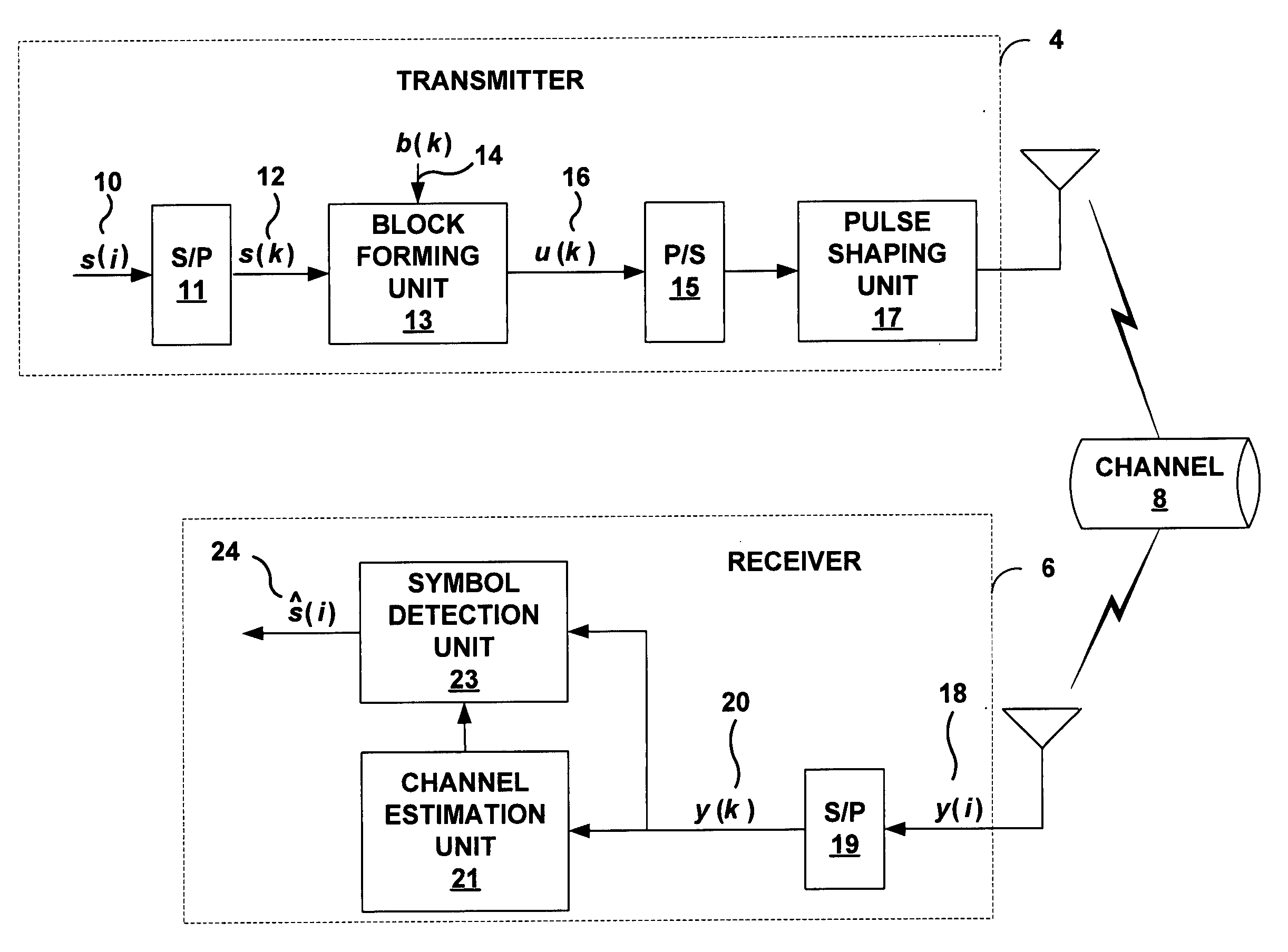
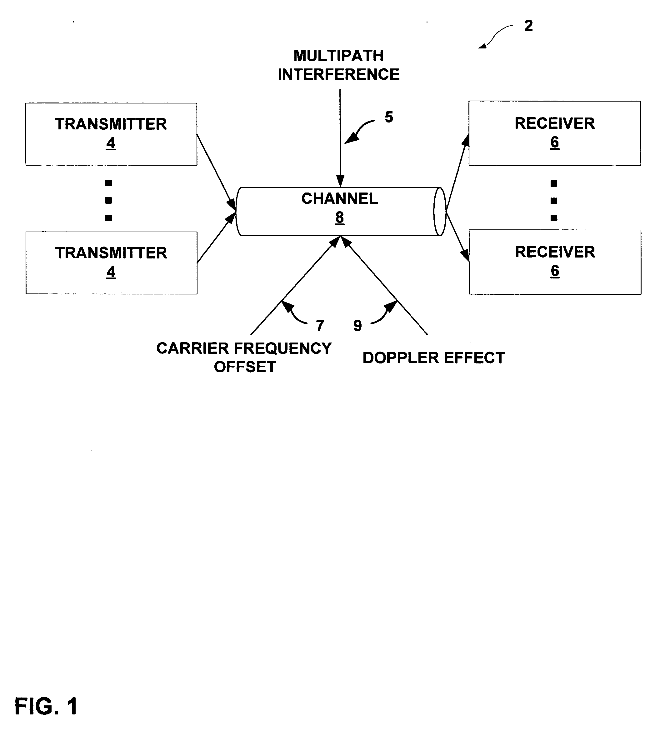
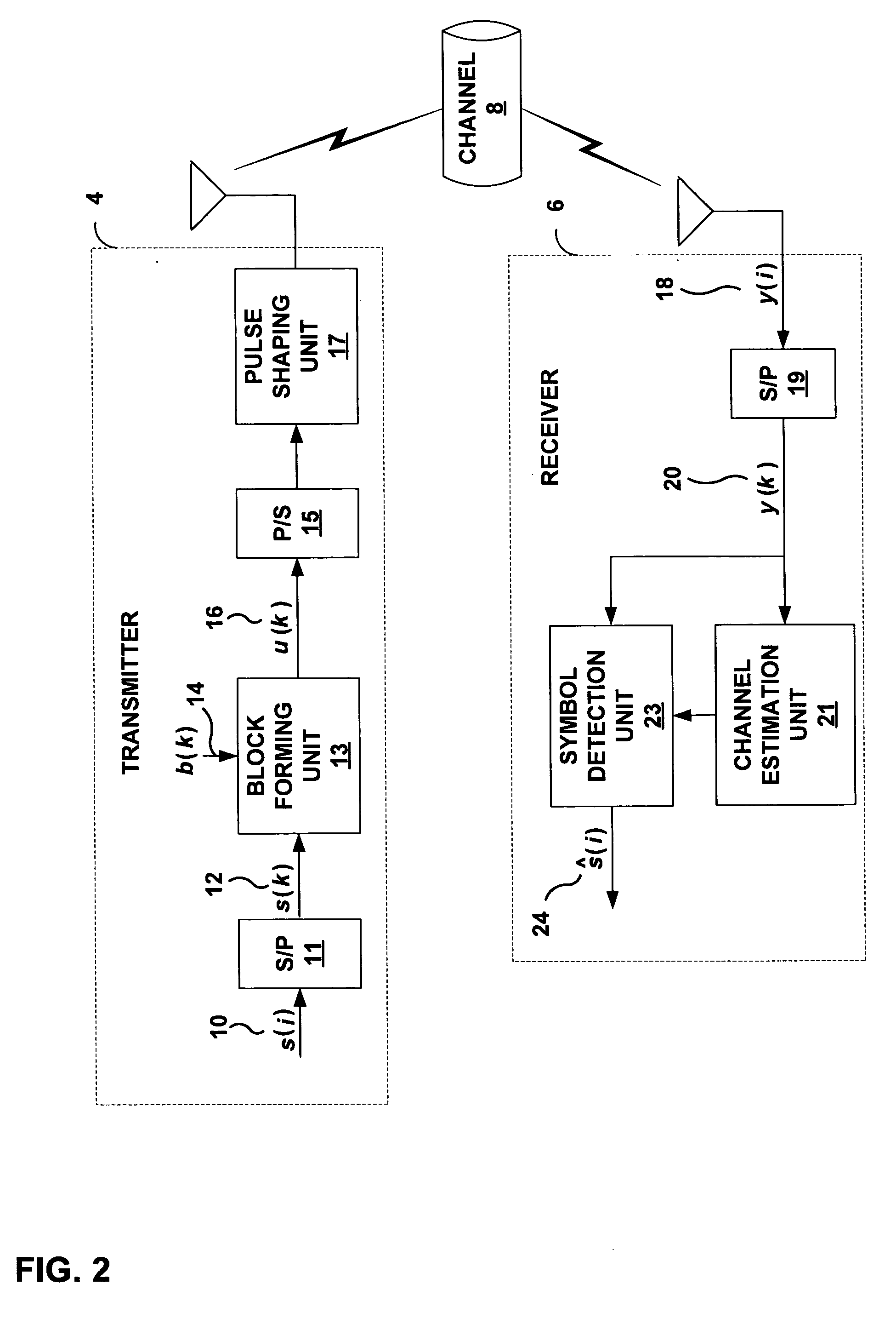
FIG. 1 is a block diagram illustrating a multi-user wireless communication system 2 in which multiple transmitters communicate with multiple receivers through time- and frequency-selective wireless communication channel 8. In general, the invention provides techniques for forming estimates of cha...


PUM


Abstract

Techniques are described for channel estimation of block transmissions over time- and frequency-selective wireless fading channels. A wireless transmitter forms blocks of symbols that include at least two blocks of training symbols separated by at least one information-bearing symbol. Each block of training symbols comprises a first block of zero symbols and a second block of zero symbols separated by at least one training symbol. Each block of training symbols is equally long and equally spaced between information-bearing symbols. The training and information-bearing symbols are transmitted with equal power, respectively. A wireless receiver receives a wireless transmission signal formed according to the blocks of symbols and forms an estimate of a wireless communication channel based on the training symbols within the received signal. The structure and selected parameters of the symbols enabling symbol detection and channel estimation to be decoupled at the receiver while maximizing the average capacity of the channel.

Description

TECHNICAL FIELD The invention relates to wireless communication systems and, more particularly, transmitters and receivers for use in wireless communications. BACKGROUND Providing reliable high data rate services, e.g. real-time multimedia services, over wireless and mobile communication channels is a paramount goal in developing coding and modulation schemes. When a data rate for wireless and mobile communication channels is high in relation to bandwidth, multipath propagation causes frequency-selective propagation while carrier frequency offsets and mobility induced Doppler shifts cause time-selectivity. Time- and frequency-selective propagation effects cause performance degradation and constitute the bottleneck for increasing data rates. In order to mitigate time- and frequency-selective propagation effects, channel state information (CSI) is collected at the receiver. CSI is acquired at a receiver either by relying on training symbols that are known a priori by the receiver o...

Claims


Application Information

Patent Timeline
Patent Type & Authority Applications(United States)
IPC IPC(8): H04K1/00H04L25/02
CPCH04L25/0242H04L25/0228
Inventor GIANNAKIS, GEORGIOS B.MA, XIAOLI
Owner RGT UNIV OF MINNESOTA
Why Eureka
Try Eureka