
Microparticle containing silicone release coatings having improved anti-block and release properties

Inactive Publication Date: 2005-01-06
RHONDIA INC
View PDF50 Cites 25 Cited by
  • Summary
  • Abstract
  • Description
  • Claims
  • Application Information

AI Technical Summary

Benefits of technology

In order to further illustrate the invention and the advantages thereof, the following non-limiting examples are given.

Problems solved by technology

Silicone polymers and copolymers have been used extensively in release compositions because they are inherently low in surface energy.
While various release compositions have been provided that limit an increase in release force, there has not been such success in lowering the release force below that which is the normal minimum of the silicone release composition.
Furthermore, silicone layers (also referred to as sheets or films) with smooth surfaces possess a high coefficient of friction such that they tend to “block” or adhere to each other.
In practice, this free silicone oil contamination can be a drawback.
For example, when the coated sheet traverses over idler rolls during subsequent processing steps (e.g., during label application), the idler rolls can slip and lose contact with the sheet.
This can result in uneven tension on the sheet web or loss of alignment.
Related problems arise when printing on the resulting silicone-coated sheet or when labels are applied to the sheet.
The ability of printing inks and solvents to adhere is impaired by the presence of free silicone oil on the surface to be printed.
Moreover, loss of alignment due to the sheet's high slip can lead to a high reject rate during printing, particularly where multiple printing passes are used and in cases where proper alignment is critical for formation of an integrated image.
Furthermore, silicone materials also tend to be costly, thus there is also a need to minimize the amount of silicone material required for making the release composition.

Method used


Image

  • Microparticle containing silicone release coatings having improved anti-block and release properties
  • Microparticle containing silicone release coatings having improved anti-block and release properties
  • Microparticle containing silicone release coatings having improved anti-block and release properties

Examples


example i

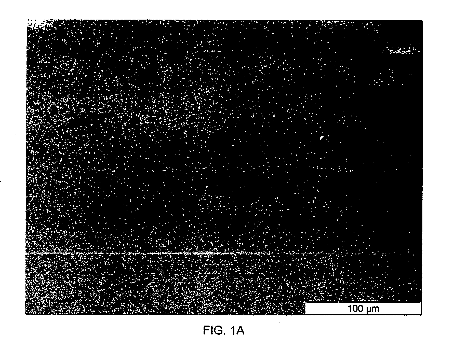
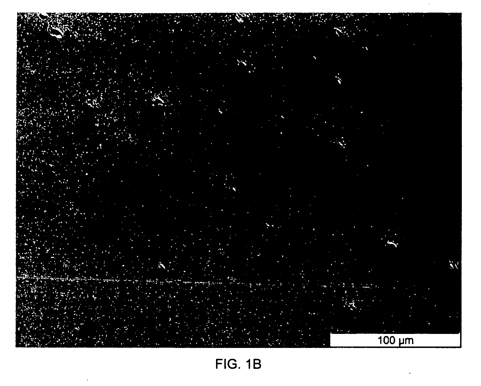
The starting formulations of the release coatings were: 60 parts by weight of a curable epoxypolyorganosiloxane compound VI, wherein n is 20 30 parts by weight of the polyorganosiloxane having compound VII, wherein r is 220 10 parts by weight of the polyorganosiloxane having compound VIII, wherein p is 200 and q is 3 2.5 parts by weight of a cationic initiator 1-3 parts polymeric microspheres

The photoinitiator employed in the test compositions was Silcolease® UV Cata211 available from Rhodia Inc., a cationic photoinitiator activated by UV radiation. The polymeric microparticles were polytetrafluoroethylene (PTFE) microsphere sold under the name FLUO HT® commercially available from Micro Powders Inc. The polymeric microspheres were prepared as a dilution in formula (VII) at 33% by weight of the formula.

The components were thoroughly mixed, applied to a polypropylene film at a coat weight of about 0.9 g / m2 using a Dixon coater, and cured under two 240 W / cm ultraviolet lamps ...


PUM

PropertyMeasurementUnit
Temperatureaaaaaaaaaa
Fractionaaaaaaaaaa
Fractionaaaaaaaaaa

Abstract

The invention is directed to a polymeric microparticle containing silicone release composition having improved slip / shear, anti-block, transfer, and lower release properties. The silicone release composition may be formed of thermal or radiation cured solventless silicone release compositions. The silicone release composition may also be formed of a UV-cationic silicone release composition. The polymeric microparticles are preferably polymeric microspheres. The invention is further directed to the use of such microparticle containing silicone release compositions to coat a substrate, and release coated substrates formed thereof.

Description

FIELD OF THE INVENTION The invention relates generally to silicone release coating compositions, the use of such silicone release coating compositions to coat a substrate, and a release coated substrate formed thereof. More particularly, the invention relates to thermal curable, radiation curable, and UV-cationic solventless silicone release coatings having improved slip / shear, transfer, anti-block, and lower release properties. BACKGROUND OF THE INVENTION Silicone release coatings or compositions are well known and the subject of many publications and patents. They are useful in many applications where one requires a relatively non-adherent surface. In such applications release compositions are coated onto a substrate, and are caused to be cured. A particularly useful application is the coating of paper, polyethylene films, and other materials that are used among other applications for providing non-stick surfaces, pressure sensitive adhesive labels, decorative laminates, and tra...

Claims


Application Information

Patent Timeline
IPC IPC(8): B29C33/64B32B9/04C08F2/46C08G59/30C08J7/04C08L83/04C09DC09D183/04
CPCB29C33/64C08G59/306C09D183/04C09J2483/005C08L2666/02C08L2666/04C09D183/06Y10T428/31663C08L2666/66
Inventor FRANCES, JEAN-MARCRADL, MICHAEL D.KERR, STUART R. IIIHOOVER, JEFFREYELLISON, JAMES G.
Owner RHONDIA INC
Learn More