
Method of manufacturing planar inductors

a technology of inductors and inductors, which is applied in the field of planar conductors, can solve the problems of difficult and expensive to produce inductors of the scale, difficult and expensive to use on many types of substrates or dielectrics, and high temperature process

Inactive Publication Date: 2005-01-13
CUSTOM ONE DESIGN
View PDF18 Cites 13 Cited by
  • Summary
  • Abstract
  • Description
  • Claims
  • Application Information

AI Technical Summary

Benefits of technology

[0018] According to another aspect of the present invention a method of forming ferromagnetic inductive cores on the surface of a dielectric material is provided. This method comprises the following steps: dipping the surface of the dielectric material in a solution containing catalytic metal particles which have a slight electrostatic dipole when in solution to help those particles attach to the dielectic material's surface; and placing the surface of the dielectric material in a first metal salt solution in metastable equilibrium with a reducing agent so as to cause a first layer containing metal to be plated upon the surface of the dielectric material containing the catalytic metal particles by a process of electroless plating.

Problems solved by technology

In the past it is been relatively difficult and expensive to produce inductive devices of the scale appropriate for use in many printed circuit boards, multichip modules, integrated circuits, or micro electromechanical (“MEM”) devices.
In the past most such ferromagnetic cores have been deposited on the MEM devices by sputtering, which is a relatively expensive, time-consuming, and high-temperature process.
The high-temperature of sputtering processes makes them impossible to use on many types of substrates or dielectrics.

Method used


Image

  • Method of manufacturing planar inductors
  • Method of manufacturing planar inductors
  • Method of manufacturing planar inductors

Examples


Embodiment Construction

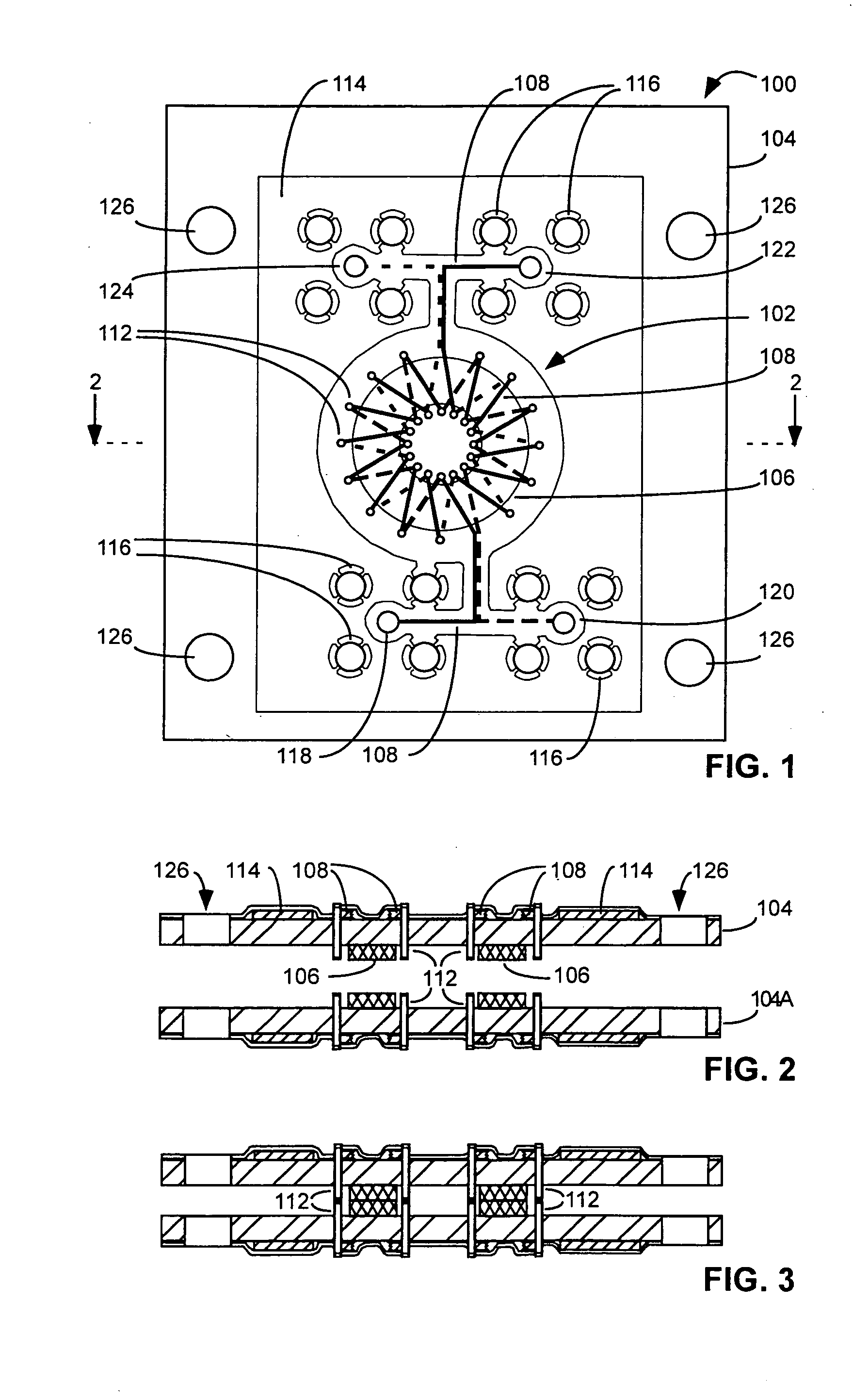
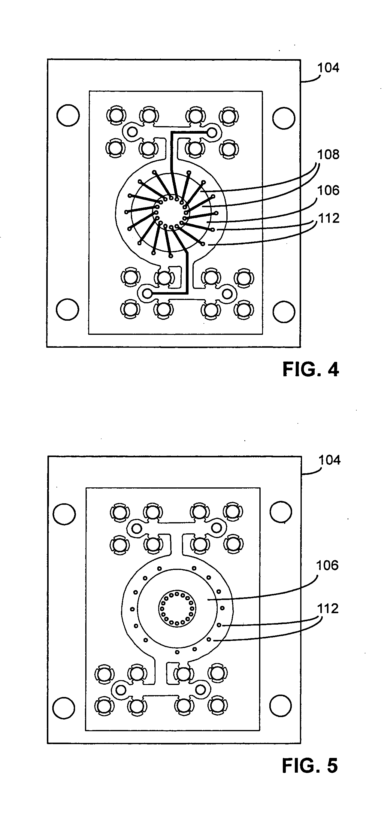
[0051]FIGS. 1 through 5 illustrate a prototype planar inductor 102 which is been built into a two layer printed circuit board 100. This inductor is of transformer having electrical properties making it suited for use in a range from approximately 100 kHz to hundreds of megahertz. In other embodiments of the invention the planar conductive cores could be of different sizes and have different number and types of windings making them suitable for use at different frequencies.

[0052]FIG. 1 is a top view of this assembly that shows its top layer 104 and its inductive core 106. This figure also shows the top layer 108 of the inductors wiring, which are shown in solid lines. The via holes 112 are used to electrically connect between the inductor's wiring on its top and bottom layers. The conductive ground plane 114 is used to provide shielding from the electromagnetic fields generated by the inductor. The via hole 118 provides a connection on the top layer of the print circuit board to the...


PUM

PropertyMeasurementUnit
Forceaaaaaaaaaa
Dielectric polarization enthalpyaaaaaaaaaa
Electrical conductivityaaaaaaaaaa

Abstract

Method of forming a ferromagnetic layer on at least one surface of a dielectric material that may be serve as an inductive core on a printed circuit board or a multichip module. Conductive leads can form two separate coils around the core to form a transformer, and a planar conducing sheet can be placed on or between one or more of the dielectric layers as magnetic shielding. The core can be formed at least in part by electroless plating, and electroplating can be used to add a thicker layer of less conductive ferromagnetic material. Ferromagnetic layers are formed by dipping the dielectric surface in a solution containing catalytic metal particles having a slight dipole, and placing the surface in a metal salt to cause a layer containing metal to be electrolessly plated upon the dielectric. Surface roughening techniques can be used before the dipping to help attract the catalytic particles.

Description

CROSS-REFERENCE TO RELATED APPLICATIONS [0001] This is a divisional application of U.S. patent application Ser. No. 09 / 904,014 filed Jul. 12, 2001, now U.S. Pat. No. 6,696,910, the contents of which are incorporated herein by reference.FIELD OF THE INVENTION [0002] The present invention relates to planar conductors for use in printed circuit boards, multichip modules, and integrated circuits, and micro electromechanical devices—and methods for making such inductors. BACKGROUND OF THE INVENTION [0003] Devices having inductive cores are important in electric and electronic apparatuses. Such devices include transformers, inductors, and electromagnets. In the past it is been relatively difficult and expensive to produce inductive devices of the scale appropriate for use in many printed circuit boards, multichip modules, integrated circuits, or micro electromechanical (“MEM”) devices. In the past such small inductive devices usually have been fabricated using a variety of mechanical oper...

Claims


Application Information

Patent Timeline
IPC IPC(8): H01F17/00H01F27/24H01F27/28H01F27/36H01F41/02H01F41/04H05K1/16H05K3/18H05K3/38H05K3/46
CPCH01F17/0013Y10T29/4913H01F27/24H01F27/2804H01F27/365H01F41/02H01F41/046H05K1/165H05K3/184H05K3/381H05K3/4614H05K2201/086H05K2201/097H05K2203/072Y10T29/49124Y10T29/49075Y10T29/49073Y10T29/4902H01F17/0033H01L2224/18H01L2224/04105H01L2224/24137H01L2224/73267H01L2924/15153H01L2224/32225H01F27/36H01F27/363
Inventor NUYTKENS, PETER R.POPEKO, ILYA E.KULINETS, JOSEPH M.
Owner CUSTOM ONE DESIGN
Learn More