Bumper construction

a bumper and construction technology, applied in the direction of bumpers, constructions, fastening means, etc., can solve the problems of affecting the appearance of bumpers, hallway walls, and other items found in supermarkets, pharmacies, department and specialty stores, which are often damaged in the same manner, and achieve easy and secure affixed, easy disassembly and assembly, and reduce installation time

Inactive Publication Date: 2005-01-13
FILTRONA EXTRUSION USA
View PDF36 Cites 26 Cited by
  • Summary
  • Abstract
  • Description
  • Claims
  • Application Information

AI Technical Summary

Benefits of technology

[0008] It is a primary object of this invention to provide several embodiments of bumper assemblies, each of which include a base member to be attached to a surface to be protected with a top or bumper which is easily and securely affixed to the base without the need for tools to reduce installation time while providing a functionally effective, active locking, assembly where the bumper element will not be easily disengaged from the base regardless of the angle of impact against the arched surface of the bumper.

Problems solved by technology

Wall surfaces in hallways, particularly in heavily trafficked areas such as hospital corridors, airport walkways and the like, are commonly exposed to impact damage resulting from misguided carts, gurneys, people movers and the like.
Likewise, grocery island cases, freezer chests, merchandise display cases, and other such items found in supermarkets, pharmacies, and department and specialty stores are often damaged in a similar manner.
Bumper guards and the like commercially available heretofore tend to compromise one or more of the foregoing criteria.
For example, in order to improve impact resistance, some products are unduly complex, making them relatively expensive to manufacture.
To minimize manufacturing costs, other products may not provide adequate protection to the surfaces on which they are mounted, or may tend to deteriorate quickly in use.
Finally, some such strip assemblies fail to hide the mounting hardware or otherwise present an unsightly appearance which is commercially undesirable.

Method used


Image

  • Bumper construction
  • Bumper construction
  • Bumper construction

Examples


Embodiment Construction

[0051] The foregoing descriptions and drawings should be considered as illustrative only of the principles of the invention. Numerous applications of the present invention will readily occur to those skilled in the art. Therefore, it is not desired to limit the invention to the preferred embodiments or the exact construction and operation of the preferred embodiments shown and described. Rather, all suitable modifications and equivalents may be resorted to, falling within the scope of the invention.

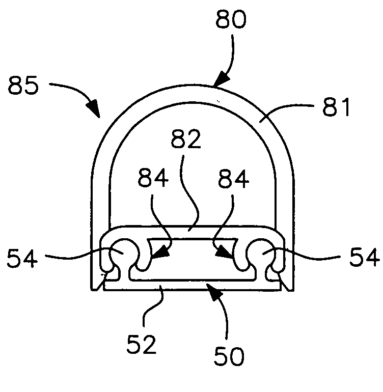
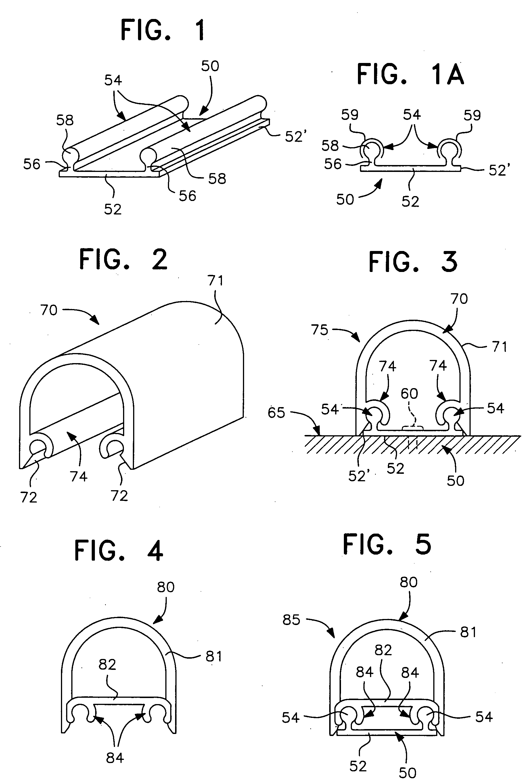
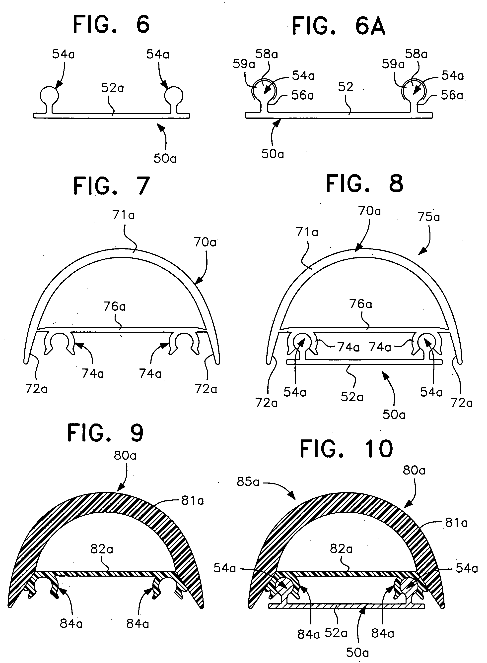
[0052] Referring now to the drawings, and more particularly to FIG. 1, a preferred form of base element according to the instant inventive concepts is designated generally by the reference numeral 50 and, although only a short portion is illustratively seen in FIG. 1, the element 50 can be of indeterminate length depending upon its application. The base element 50 is preferably extruded, either from a “rigid” plastics material such as PVC or from aluminum, although other materials may be...


PUM


Abstract

A protective bumper strip assembly for protecting surfaces such as walls, display cases, furniture, and the like, from damage caused by inadvertent impact. The protective bumper strip assembly comprises a base member attachable to a supporting surface to be protected and a bumper that is press-fit or snap-fit to the base member. The press-fit interconnection is formed from male and female interconnecting elements to form a mechanical connection therebetween. The male and female interconnecting elements include a high friction material to prevent slippage therebetween when the bumper is impacted. The interengagement between the base member and the bumper requires no additional interconnecting or attachment members. The base member includes a pair of elongated arcuate male members which receive arcuate complementary female interconnecting elements extending from the bumper. Free end portions of the assembly may include cap elements of flat or spherical shape to enclose the ends of the strip assemblies.

Description

[0001] This is a complete application claiming benefit of provisional application Ser. No. 60 / 473,467 filed May 28, 2003.BACKGROUND OF THE INVENTION [0002] 1. Field of the Invention [0003] This invention relates generally to protective bumper systems, and relates more particularly to strip assemblies for protecting surfaces such as walls, display cases, furniture, and the like, from damage caused by inadvertent impact. [0004] 2. Discussion of the Prior Art [0005] Wall surfaces in hallways, particularly in heavily trafficked areas such as hospital corridors, airport walkways and the like, are commonly exposed to impact damage resulting from misguided carts, gurneys, people movers and the like. Likewise, grocery island cases, freezer chests, merchandise display cases, and other such items found in supermarkets, pharmacies, and department and specialty stores are often damaged in a similar manner. [0006] To minimize such damage, bumper guards or strip assemblies of various designs have...

Claims


Application Information

Patent Timeline
Patent Type & Authority Applications(United States)
IPC IPC(8): E04F19/02F16B12/24
CPCE04F19/026F16B12/24E04F19/028
Inventor MCSHARRY, BRIANKLOPP, PHILQUARTARONE, FRANK
Owner FILTRONA EXTRUSION USA
Why Eureka
Try Eureka