
Air conditioning system

Inactive Publication Date: 2005-01-13
HITACHI APPLIANCES INC
View PDF5 Cites 37 Cited by
  • Summary
  • Abstract
  • Description
  • Claims
  • Application Information

AI Technical Summary

Benefits of technology

[0005] It is an object of the present invention to provide an air conditioning system arranged to use a power line as communication means which saves resources and installing work.

Problems solved by technology

The topology of the wiring and piping is different in each work, so that the renewal work is so complicated.
The air conditioning system arranged to use the power line as transmission means is restrictive in its transmission rate and topology.
This leads to a disadvantage of lowering the response and making the overall system more costly because of a special connecting means to be required therefor.

Method used


Image

  • Air conditioning system
  • Air conditioning system
  • Air conditioning system

Examples


first embodiment

[0024] the present invention will be described with reference to FIGS. 1 to 7.

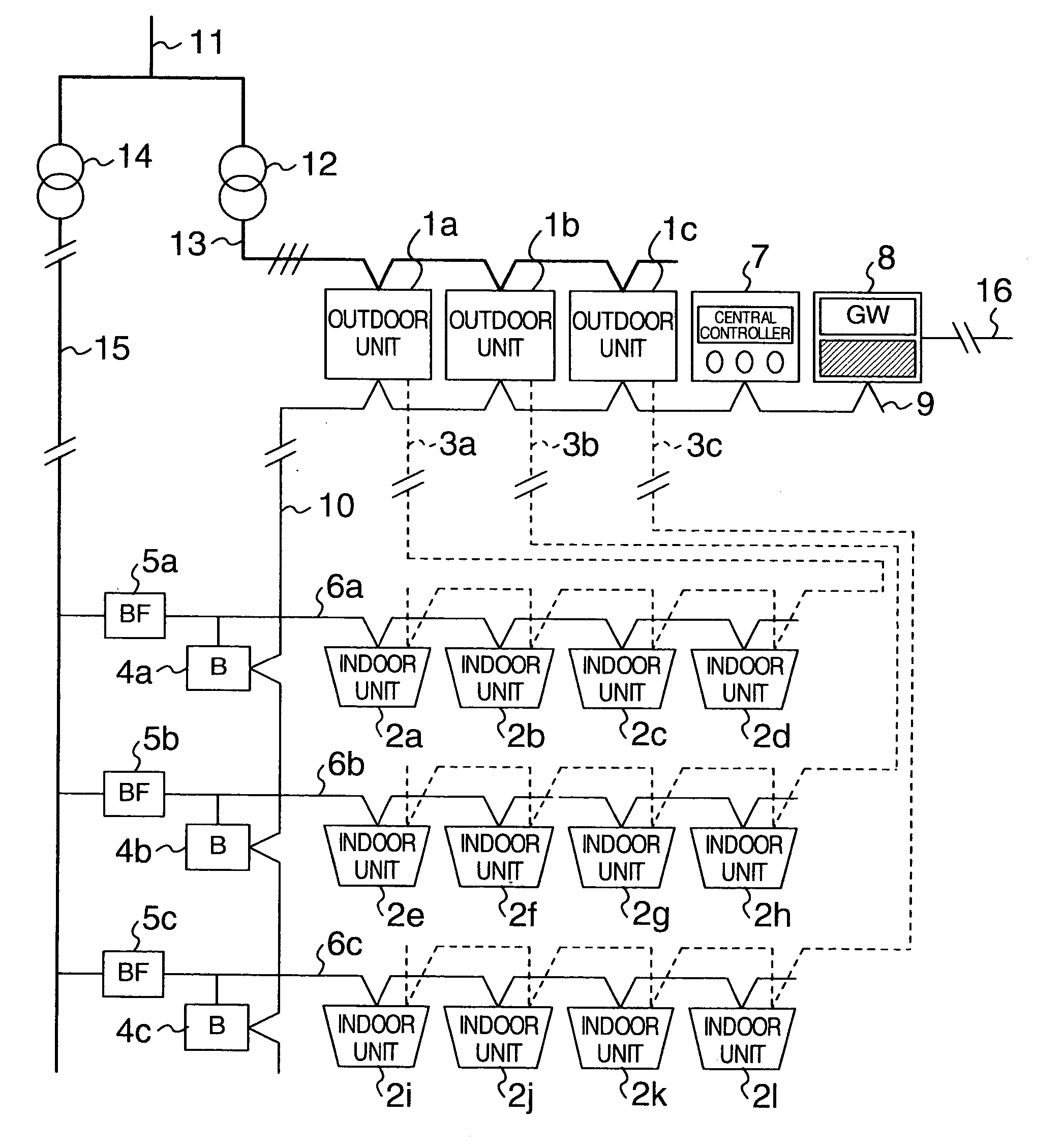
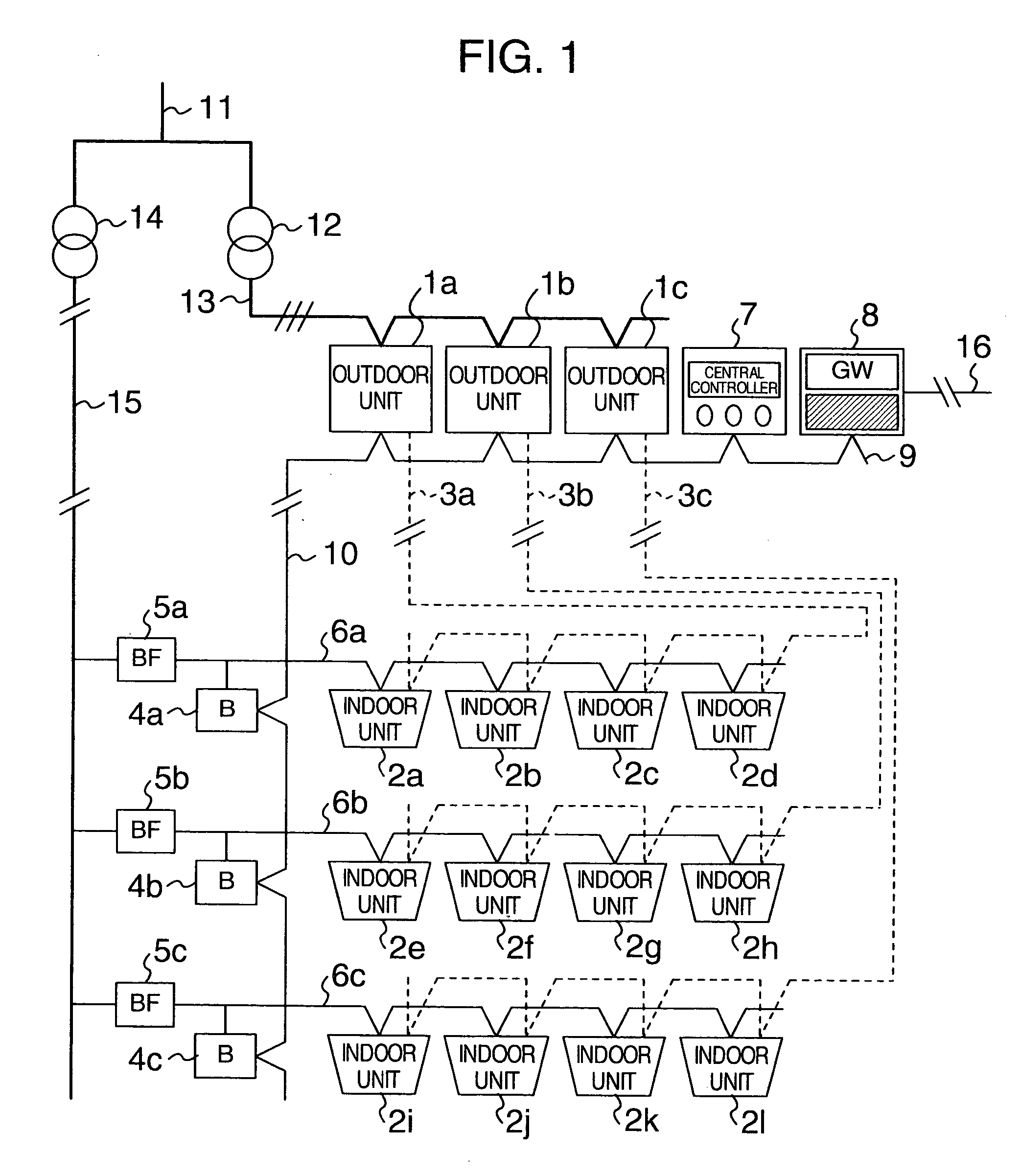
[0025]FIG. 1 is a schematic diagram showing an overall arrangement of an air conditioning system arranged to use a power line as a communication means according to the first embodiment of the present invention.

[0026] In FIG. 1, reference numbers 1a to 1b denote outdoor units, reference numbers 2a to 21 denote indoor units, reference numbers 3a to 3c denote refrigerant pipings, reference numbers 4a to 4c denote bridges, reference numbers 5a to 5c denote blocking filters, reference numbers 6a to 6c denote branch power lines, a reference number 7 denotes a central controller, a reference number 8 denotes a gateway, a reference number 9 denotes a transmission line through which data may be transmitted at high speed, a reference number 10 denotes a connecting wire between communication areas, a reference number 11 denotes a power-receiving line, a reference number denotes a three-phase transformer, a reference...

second embodiment

[0056] In turn, the description will be oriented to the present invention with reference to FIGS. 8 to 11.

[0057]FIG. 8 is a schematic diagram showing an arrangement of an air conditioning system according to the second embodiment of the present invention. The different respect of the second embodiment from the first embodiment is a connection of the indoor units 500a to 500d through adapters 600a to 600d in addition to the connection of the indoor units 2a to 2h. Like the first embodiment, the second embodiment is equipped with the refrigerant piping, though it is not shown in FIG. 8.

[0058] Each of the indoor units 500a to 500d has the same arrangement as the conventional indoor unit. The indoor unit supplies the transmission data and the electric power through the effect of the adapter 600.

[0059]FIG. 9 is a schematic diagram showing an internal arrangement of the indoor unit 500 included in the second embodiment of the present invention. The indoor unit 500 corresponds to one of ...


PUM


Abstract

An air conditioning system is arranged to use a power line for communication. The air conditioning system includes one or more indoor units, one or more outdoor units, and a system controller for controlling the indoor units or outdoor units and executes communications between the indoor units and the outdoor units as overlapping a signal on the power line for supplying electric power. The outdoor units are connected with the system controller through a leased communication line. The indoor unit provides a power line communication device being connected with the power line. The outdoor unit provides a leased communication device being connected with the leased communication line. A bridge is also provided for connecting the leased communication line and the power line. The control information is exchanged mutually between the indoor units, the outdoor units and the system controller through the power line.

Description

BACKGROUND OF THE INVENTION [0001] The present invention relates to a control system arranged to overlap a high-frequency signal on a power line when performing communications on a power line. [0002] The conventional air conditioning system is composed to have one or more outdoor units, one or more indoor units, a three-phase and a single-phase power lines for supplying electric power to these units, a refrigerant piping for exchanging refrigerant between the indoor units and the outdoor units, a bus wiring transmission line for exchanging control information between the indoor units and the outdoor units, and a remote controller for operating the indoor units. The control information of the air conditioning system includes an indication of on or off of a power supply or “in operation” of the indoor unit, a set room temperature and a current temperature, operating conditions of the outdoor unit and the indoor unit, and so forth. These pieces of data also include a header composed of...

Claims


Application Information

Patent Timeline
IPC IPC(8): F24F11/02F24F11/00
CPCF24F1/0003F24F2011/0067F24F11/0009F24F11/30F24F11/54F24F11/52F24F11/72F24F11/58F24F11/871F24F11/86
Inventor KOJIMA, YASUYUKIAKIYAMA, NOBORUONAKA, TAKESHIYAMAUCHI, TATSUMITANIGUCHI, KOICHITOKUSHIGE, KOICHIBUNKOU, NORIYUKISATO, KEIJI
Owner HITACHI APPLIANCES INC
Learn More