Diagnostic apparatus for an exhaust gas sensor

a technology of diagnostic equipment and exhaust gas, which is applied in the direction of electrical control, process and machine control, instruments, etc., can solve the problems of difficult to keep the frequency of composite output signals constant, the evaluation precision may deteriorate, and the control unit cannot perform the correct control of the stoichiometric air-fuel ratio upon the internal combustion engine, so as to prevent the increase of emitted amount, maintain detection precision, and suppress the effect of catalyst purification ra

Active Publication Date: 2005-01-13
HONDA MOTOR CO LTD
View PDF8 Cites 13 Cited by
  • Summary
  • Abstract
  • Description
  • Claims
  • Application Information

AI Technical Summary

Benefits of technology

According to yet further aspect of the invention, the deterioration failure diagnostic device additionally has air-fuel ratio controlling means for controlling an air-fuel ratio to be supplied to the internal-combustion engine so as to converge the air-fuel ratio to a predetermined value based on the output of the exhaust gas sensor. The fuel injection amount is corrected in accordance with a feedback coefficient that is determined based on the output of the exhaust gas sensor. According to this aspect of the invention, the fuel injection amount is corrected such that a drift toward rich or lean which is caused by applying the detecting signal to the fuel injection amount can be suppressed. As a result, it is possible to suppress the decrease of the catalyst purification rate that may occur due to the detection method of the present invention so as to maintain the detection precision while preventing the increase of the emitted amount of the harmful constituents contained in the exhaust gas.
According to yet further aspect of the invention, the feedback coefficient is determined based on an output of either an exhaust gas sensor disposed upstream of a catalytic converter or an exhaust gas sensor disposed downstream of the catalytic converter or outputs from both of the exhaust gas sensors disposed upstream and downstream of the catalytic converter. According to this aspect of the invention, the fuel injection amount is corrected such that a drift t

Problems solved by technology

Therefore, when the exhaust gas sensor cannot indicate a correct air-fuel ratio due to its degradation failure, the control unit cannot perform a correct control of the stoichiometric air-fuel ratio upon the internal-combustion engine.
Furthermore, because the signal that responds to the oxygen level of the exhaust gas is influenced by an op

Method used


Image

  • Diagnostic apparatus for an exhaust gas sensor
  • Diagnostic apparatus for an exhaust gas sensor
  • Diagnostic apparatus for an exhaust gas sensor

Examples


Embodiment Construction

1. Description of Functional Blocks

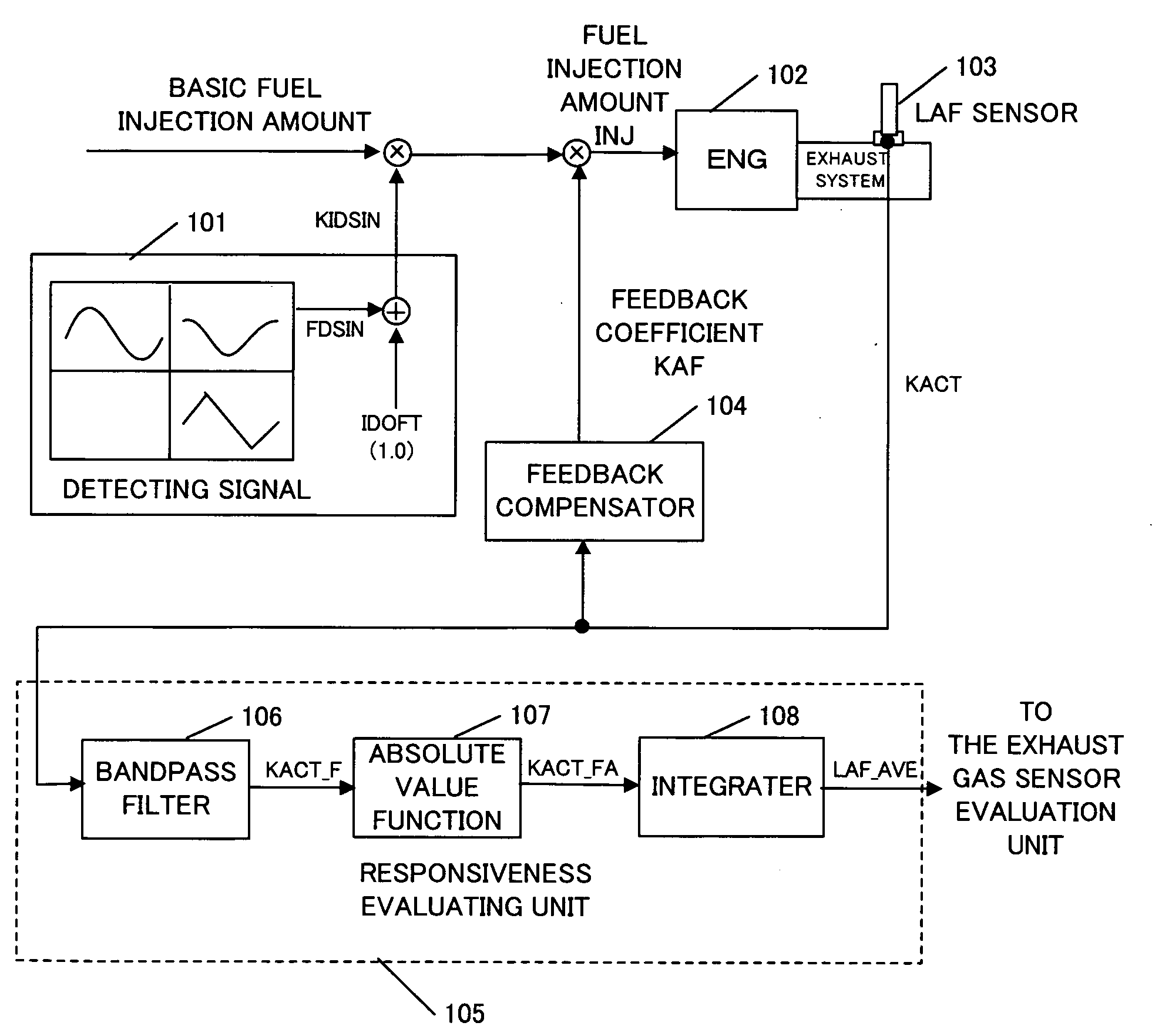
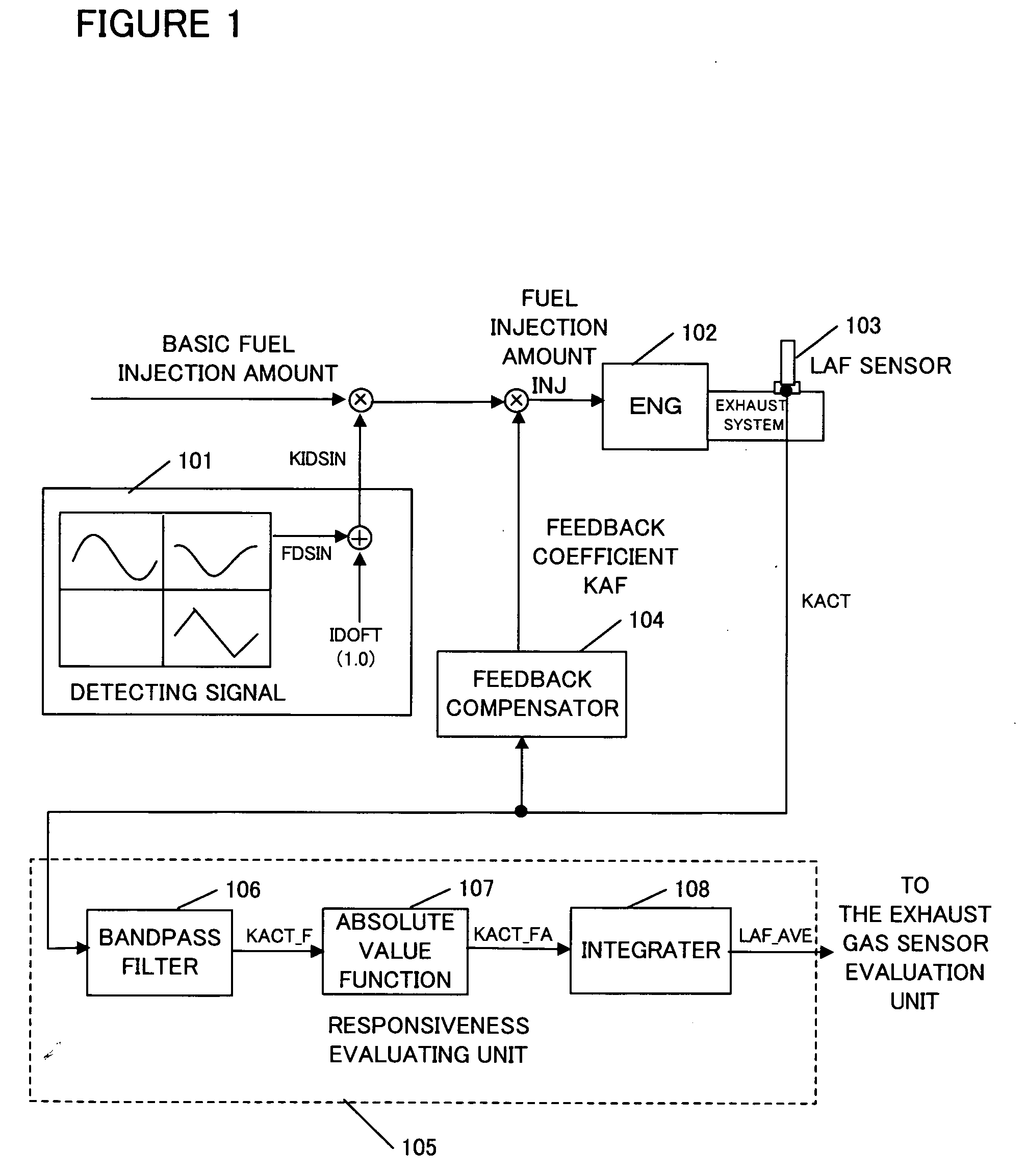
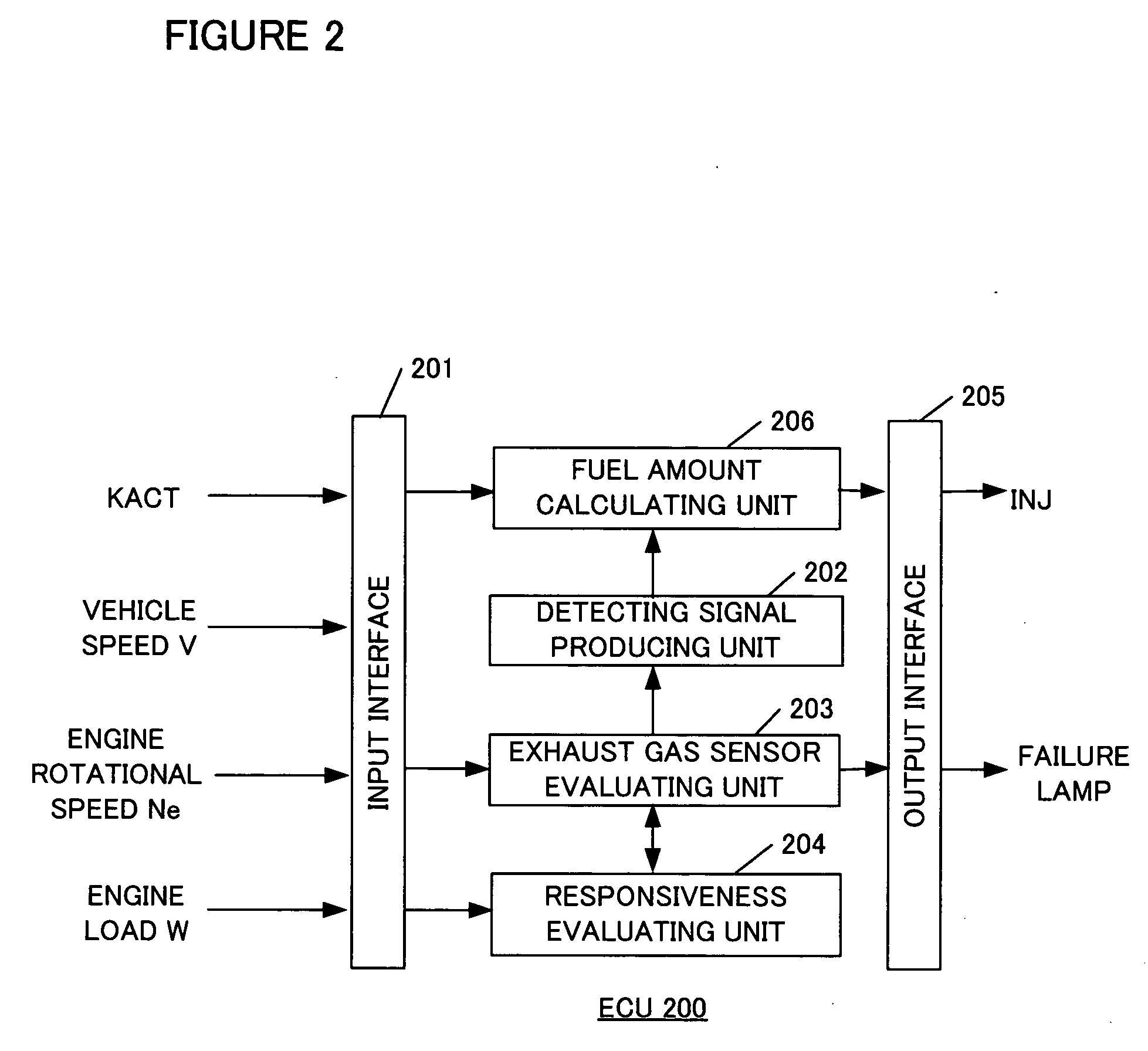
Each functional block will be described with reference to FIG. 1 and FIG. 2. FIG. 1 is a schematic diagram of an overall structure for describing a concept of the present invention.

A detecting signal producing unit 10 has a function of producing a given, detecting signal KIDSIN in which a trigonometric function wave FDSIN or the like is superimposed on an offset value IDOFT. A responsiveness evaluating unit 105 performs band-pass filtering of KACT, output from a linear air-fuel ratio sensor (hereinafter referred to as an LAF sensor) 103. KACT is an equivalent ratio proportional to the fuel-air ratio F / A and takes a value of 1.0 for the stoichiometric air-fuel ratio. The unit 105 converts the filtered value to an absolute value, integrates the converted values over a given time period and transmits the integrated value to an exhaust gas sensor evaluating unit. The exhaust gas sensor evaluating unit determines degradation failure of the exhaust ...


PUM


Abstract

A deterioration failure diagnostic apparatus for an exhaust gas sensor has a higher detection precision and a wider detection range against the deterioration failure of the exhaust gas sensor. An exhaust gas sensor is disposed in an exhaust gas pipe of an internal-combustion engine for producing an output corresponding to components of exhaust gas of the engine. The apparatus has a device for producing a detecting signal, which is multiplied to a basic fuel injection amount used at a normal operation to produce a fuel injection amount to be used for determining a condition of the exhaust gas sensor. The apparatus includes a device for extracting a frequency response corresponding to the detecting signal from an output of the exhaust gas sensor. The output is in response to the calculated fuel injection amount. The condition of the exhaust gas sensor is determined based on the extracted frequency response.

Description

BACKGROUND OF THE INVENTION This invention relates to a diagnostic device for detecting a degradation failure of an exhaust gas sensor disposed in an exhaust gas pipe of an internal-combustion engine. An exhaust gas sensor is generally disposed in an exhaust gas pipe of an internal-combustion engine of a vehicle in order to measure components of exhaust gas. The exhaust gas sensor outputs an air-fuel ratio of the exhaust gas. Based on this output value, a control unit of the internal-combustion engine controls a stoichiometric air-fuel ratio of fuel to be supplied to the internal-combustion engine. Therefore, when the exhaust gas sensor cannot indicate a correct air-fuel ratio due to its degradation failure, the control unit cannot perform a correct control of the stoichiometric air-fuel ratio upon the internal-combustion engine. There are disclosed some techniques for detecting a degradation failure of such exhaust gas sensor. The Japanese Patent Application Unexamined Publicati...

Claims


Application Information

Patent Timeline
IPC IPC(8): F02D45/00F01N3/00F01N11/00F02D41/14F02D41/22F02D41/30G01M99/00
CPCF01N2550/00F02D41/222F02D41/1495
Inventor MAKI, HIDETAKA
Owner HONDA MOTOR CO LTD
Why Eureka
Try Eureka