Cross-linked thermoplastic tubing

a thermoplastic tubing and cross-linked technology, applied in the field of tubing, can solve the problems of rubber hose installation, additional labor and expense,

Inactive Publication Date: 2005-01-13
COOPER TECH SERVICES
View PDF15 Cites 58 Cited by
  • Summary
  • Abstract
  • Description
  • Claims
  • Application Information

AI Technical Summary

Benefits of technology

[0007] The tubing of the present invention includes at least one layer of a thermoplastic cross-linked by high-level radiation. In a first embodiment, the tubing includes a layer of cross-linked polyamide. In one example, the tubing includes an inner layer of a fluoropolymer, a middle adhesive layer essentially made of a fluoropolymer, and an outer layer of cross-linked polyamide. The polyamide layer can include a cross-linking aid to assist the polyamide in cross-linking when exposed to high-level radiation. In one example, the cross-linking aid is triallyliscocyanurant or TAIC. The other layers can include an additive to prevent these layers from cross-linking when exposed to high-level radiation.

Problems solved by technology

However, there are several drawbacks to employing rubber hoses.
Additionally, a curing or fixing process is needed after extrusion to maintain the elastic properties of the tubing, requiring additional labor and expense.

Method used


Image

  • Cross-linked thermoplastic tubing
  • Cross-linked thermoplastic tubing
  • Cross-linked thermoplastic tubing

Examples


second embodiment

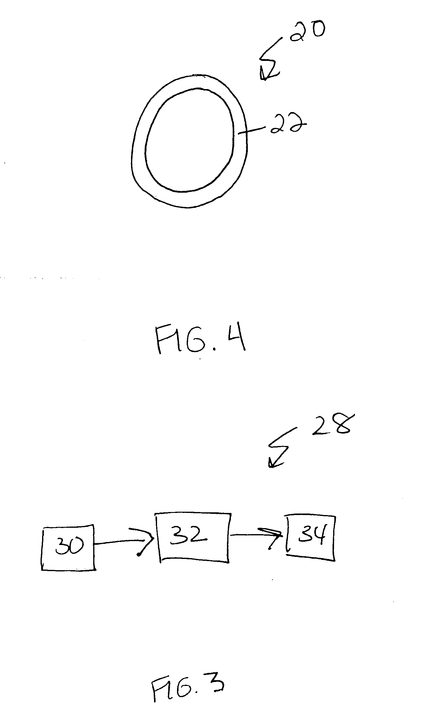
[0028]FIG. 4 schematically illustrates the tubing 20 of the present invention. In this embodiment, the tubing 20 includes only a single layer of cross-linked polyamide 22. The single layer of the tubing 20 can be polyamide 11, polyamide 12, polyamide 6, polyamide 4,6, polyamide 6,6 or any other polyamide. The tubing 20 can also include a cross-linking aid as described above. Additionally, the tubing 20 can be corrugated.

third embodiment

[0029]FIG. 5 schematically illustrates the tubing 40 of the present invention. The tubing 40 includes a cross-linked polyamide layer or a cross-linked polyolefin layer 44 applied over a steel tube 42. In one example, the polyolefin is polyethylene. The cross-linked polyamide layer or the cross-linked polyolefin layer 44 can be applied via extrusion, injection molding, powder coating, painting or other applications processes prior to cross-linking. The polyamide layer or polyolefin layer 44 is cross-linked by exposure to high-level radiation. However, it is to be understood that other cross-linked thermoplastics can be layered over the steel tube 42.

fourth embodiment

[0030]FIG. 6 schematically illustrates the tubing 50 of the present invention. The tubing 50 includes a first layer 54 of a cross-linked thermoplastic and a second layer 52 of a thermoplastic. The first layer 54 can be polyamide, aromatic nylon, polyolefin (such as polyethylene or polypropylene), polyvinyl chloride or polyester. Examples of polyamides are polyamide 11, polyamide 12, polyamide 6, polyamide 4,6, polyamide 6,6 or any other polyamide. When exposed to high-level radiation, the first layer 54 cross-links to provide increased chemical and temperature resistance. Although the first layer of cross-linked thermoplastic 54 is illustrated as the outer layer, it is to be understood that the layer of cross-linked thermoplastic 54 can be any layer in the tubing 50. It is also to be understood that other layers can be employed in addition to the first layer 54 and the second layer 52. For example, an adhesive layer (not shown) can be utilized between the first layer 54 and the seco...


PUM

PropertyMeasurementUnit
thicknessaaaaaaaaaa
thicknessaaaaaaaaaa
thicknessaaaaaaaaaa

Abstract

A tubing includes a layer of cross-linked polyamide. The polyamide layer can include a cross-linking aid, such as triallyliscocyanurant or TAIC, to assist in cross-linking the layer. When the polyamide layer is exposed to high-level radiation, the polyamide layer cross-links to provide a layer having high temperature resistance and high glycol resistance. In another embodiment, the tubing includes a first layer of a cross-linked thermoplastic and a second layer to form a multi-layer tubing. The thermoplastic of the first layer can be polyamide, aromatic nylon, polyolefins, polyvinyl chloride or polyester.

Description

[0001] The patent application claims priority to German Patent Application DE 103 11 500.5 filed on Mar. 15, 2003. BACKROUND OF THE INVENTION [0002] The invention relates generally to a tubing having at least one layer of cross-linked thermoplastic. [0003] A known tubing disclosed in German Patent Application DE 195 35 489 C1 has three layers. The tubing has an inner layer of polyvinylidine fluoride (PVDF), an outer layer of polyamide (PA), preferably polyamide 11 or polyamide 12, and a middle layer that adheres the inner layer and the outer layer. This known type of tubing is commonly used as a cooling water tubing in engine coolant systems. It is important that the outer polyamide layer have both high temperature resistance and high glycol resistance. [0004] The technical properties of polyethylene (PE) tubes can be improved by cross-linking. For example, cross-linking provides polyethylene with high temperature and chemical resistance. Polyethylene tubes are commonly used as unde...

Claims


Application Information

Patent Timeline
Patent Type & Authority Applications(United States)
IPC IPC(8): B32B1/08B32B27/26B32B27/34F16L9/128F16L9/133
CPCB32B1/08B32B27/26Y10T428/1393F16L9/121B32B27/34B32B27/08B32B2305/72B32B2310/08B32B2377/00B32B2597/00
Inventor ROLOFF, DIETMAR
Owner COOPER TECH SERVICES
Why Eureka
Try Eureka