Gravity potential powered elevator

a gravity potential and elevator technology, applied in the direction of elevators, building lifts, transportation and packaging, etc., can solve the problems of large energy loss, limited motor efficiency, and high and achieve the effect of reducing the cost of permanent magnet dc motor and vector inverter

Inactive Publication Date: 2005-01-13
LEE KWAN CHUL
View PDF7 Cites 18 Cited by
  • Summary
  • Abstract
  • Description
  • Claims
  • Application Information

AI Technical Summary

Problems solved by technology

During this process a large magnitude of energy loss occurs because of the limited efficiency of the motor.
But the high cost of the permanent magnet DC motor and vector inverter is an obstacle for the application and the energy consumption of the motors still remained.

Method used


Image

  • Gravity potential powered elevator
  • Gravity potential powered elevator
  • Gravity potential powered elevator

Examples


Embodiment Construction

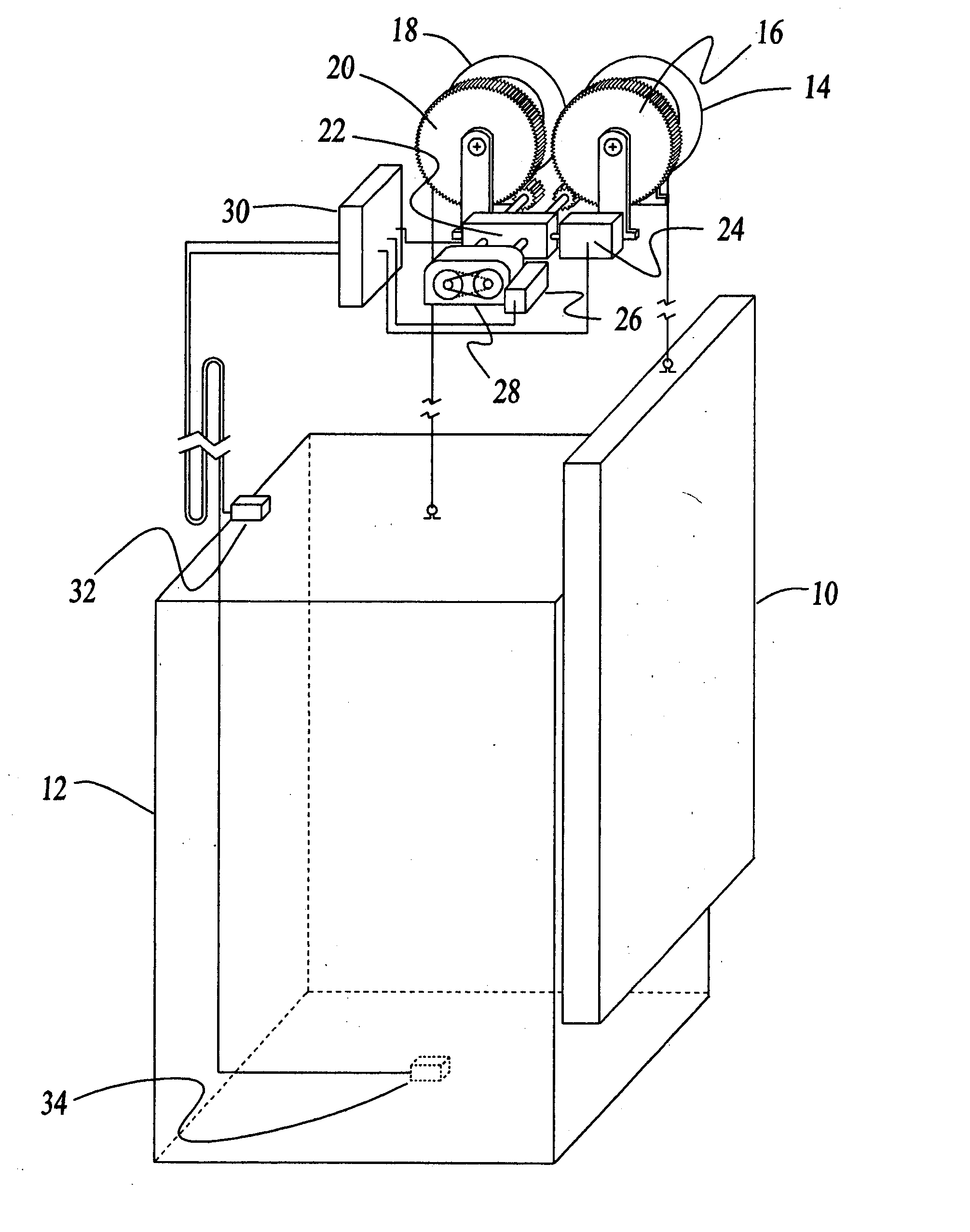
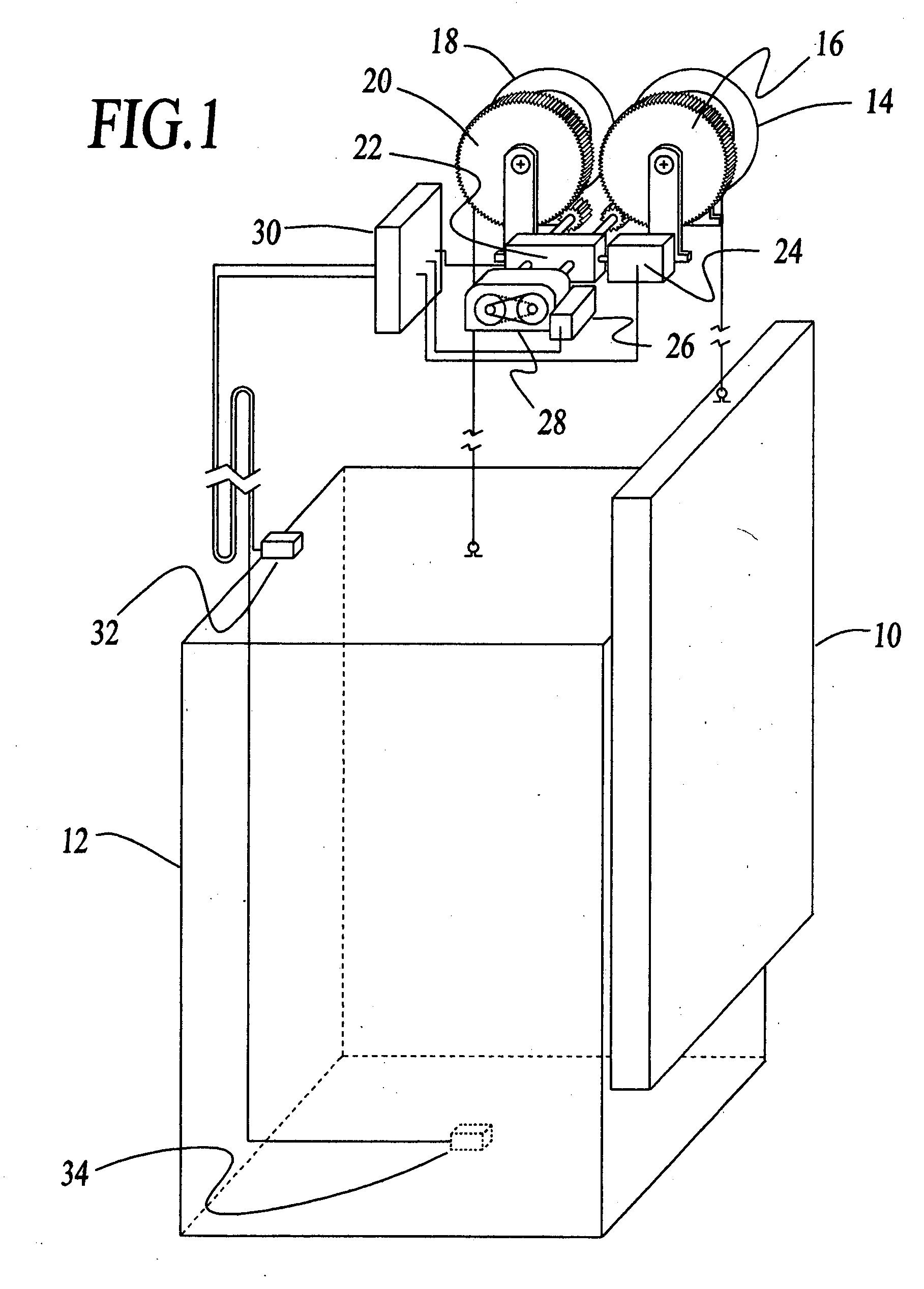
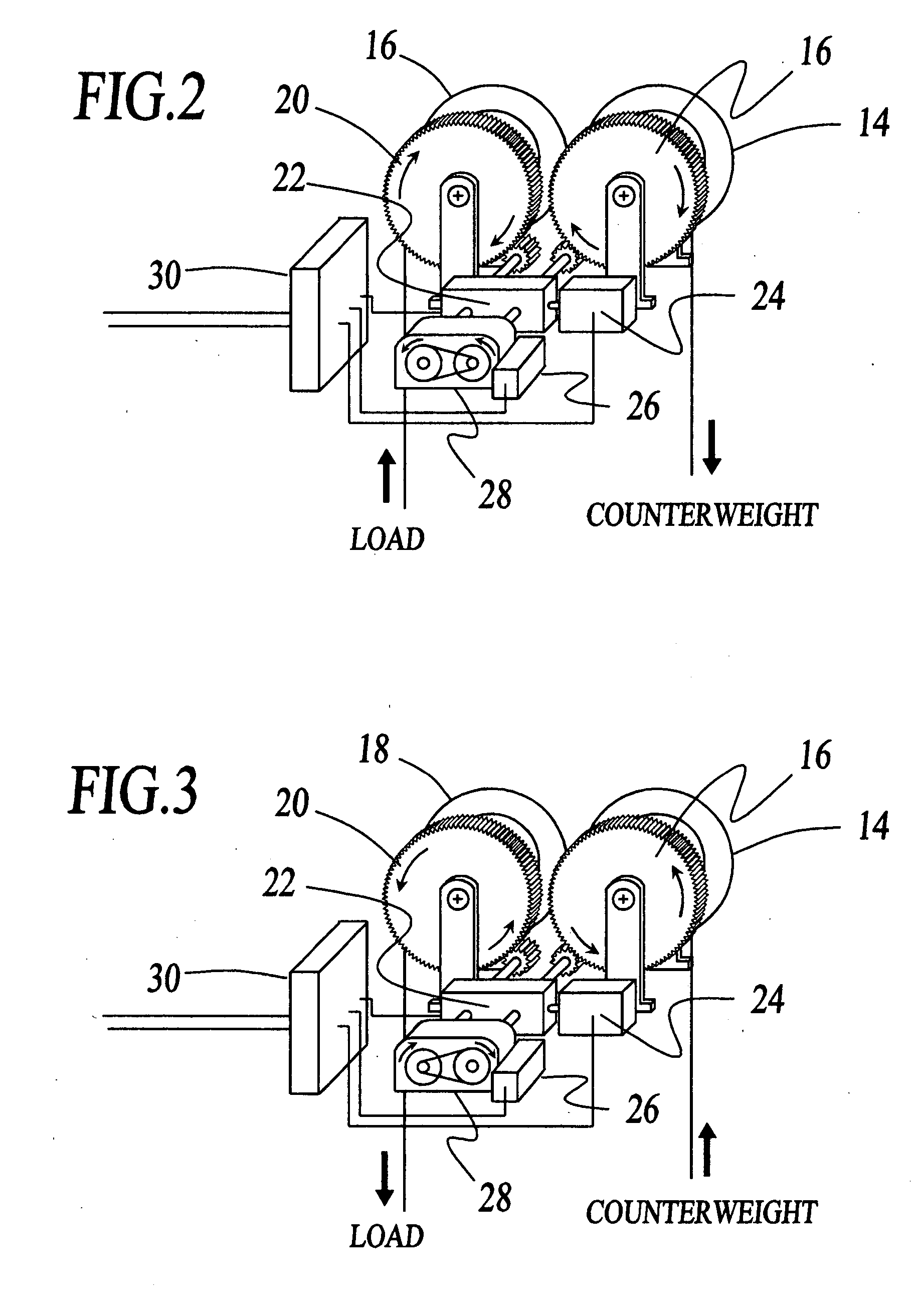
[0030] The principle of the invention is same as the principle of lever. One can give a simplified explanation as follow. When the load weight is heavier than counterweight 10 and the elevator 12 is heading upward, the gear rate should be set at a ratio as shown in the FIG. 2 so that the smaller gravity force of counterweight can drive the gearbox 28 and the elevator can move upward. On the other hand when the counterweight is heavier than load and the elevator is heading downward, the gear rate should be set at a ratio as shown in the FIG. 3 so that the smaller gravity force of load weight can drive the gearbox and the elevator can move downward. Opposite cases of these two examples are easier to understand because in those cases larger gravity forces drive the gearbox and load. One of important parts in this system is the feedback control of the variable gearbox because after the initial movement of the elevator it will move at a constant acceleration.

[0031] The real weight of co...


PUM


Abstract

An elevator system using a variable gearbox(28) and a feedback control(30) for the generation of driving force in up and down directions from the potential difference of the load(12) and the counterweight(10). The invention connects load and counterweight by a feedback controlled variable gearbox. The operation of the invention is consist of three steps: first, measuring the weight of load, second, setting the initial rate of the variable gearbox using the weight information so that enough amount of gravitational force can act in the desired direction, then the car will move at a constant acceleration, third, controlling the rate of the variable gearbox using the signal from the position sensor(32) in order to optimize the speed and position of the car. The invention will get rid of the main driving motor and reduce a lot of energy consumption.

Description

CROSS-REFERENCE TO RELATED APPLICATIONS [0001] A: U.S. Pat. No. 4,766,977, Yamasaki, Aug. 30, 1988 [0002] B: U.S. Pat. No. 6,450,299, Lysaght, Sep. 17, 2002 [0003] C: U.S. Pat. No. 5,828,014, Coto, Oct. 27, 1998 [0004] D: U.S. Pat. No. 6,526,368, Coste, Feb. 25, 2003FEDERALLY SPONSORED RESEARCH [0005] Not Applicable SEQUENCE LISTING OR PROGRAM [0006] Not Applicable BACKGROUND OF THE INVENTION—FIELD OF INVENTION [0007] This invention relates to new energy saving type elevators, specifically to such elevators that use the gravity as the driving force. BACKGROUND OF THE INVENTION [0008] (1) Prior Art [0009] Most of the modern electric elevators utilize the counterweight as a balancing weight for the reduction of the driving force but the load weight varies with number of passengers or amount of load so the mass difference between load weight and counterweight is inevitable. Therefore the mechanism of a conventional electric elevator always uses additional driving device such as electri...

Claims


Application Information

Patent Timeline
Patent Type & Authority Applications(United States)
IPC IPC(8): B66B9/00B66B11/04
CPCB66B11/0484
Inventor LEE, KWAN-CHUL
Owner LEE KWAN CHUL
Why Eureka
Try Eureka