Piezoelectric motor

a technology of piezoelectric motors and motors, applied in piezoelectric/electrostrictive/magnetostrictive devices, electrical apparatus, piezoelectric/electrostrictive/magnetostrictive devices, etc., can solve problems such as large power density, and achieve the effects of no energy loss, simple supply and high efficiency

Inactive Publication Date: 2005-01-13
MINISWYS
View PDF27 Cites 9 Cited by
  • Summary
  • Abstract
  • Description
  • Claims
  • Application Information

AI Technical Summary

Benefits of technology

[0024] It is been shown that an arrangement in which the longitudinal oscillation runs essentially parallel to the movement direction (or parallel or tangentially to the surface to be moved) runs more smoothly and at a higher efficiency compared to an essentially perpendicular arrangement according to the state of the art, which may be explained by the weaker impacts perpendicular to the surface to be driven.
[0025] If, in each case, an equal piezoelement is coupled on both sides of the resonator region, and the two piezoelements are polarized oppositely to one another, then oscillations of the piezoelement in the direction of its thickness hardly effect the resonator region so that no energy is lost by friction upon movement of the horn tip transversely to the movement direction.
[0026] For the electrical polarization of all piezoelements arranged on a drive plate, the drive plate may be exploited as one of the two electrical terminals if the drive plate consists of an electrically conductive material and the piezoelements are assembled thereon with an electrically conducting adhesive. A very simple supply results if two identical drive plates are used and the piezoelements are arranged therebetween and supplied via the two drive plates. With such an embodiment form, one may supply all piezoelements with only two electrical connections to the two electrically conducting drive plates, which, in particular, is advantageous for the smallest designs of the piezoelectric drive. The location of the electrical connections is to be selected such that no negative influencing of the oscillation behavior occurs.
[0027] In an embodiment with two drive plates, in order to reduce any occurring oscillation of the horn tips in the direction of the thickness of the drive plate, it is possible to connect the horn tips of each resonator region of the two drive plates to one another via a suitable spacer. This spacer or another suitable element may simultaneously be used for influencing the oscillation behaviour. Furthermore, the friction surface may be increased by way of a spacer.

Problems solved by technology

Furthermore, they have a large power density on account of the compact construction.

Method used


Image

  • Piezoelectric motor
  • Piezoelectric motor
  • Piezoelectric motor

Examples


Embodiment Construction

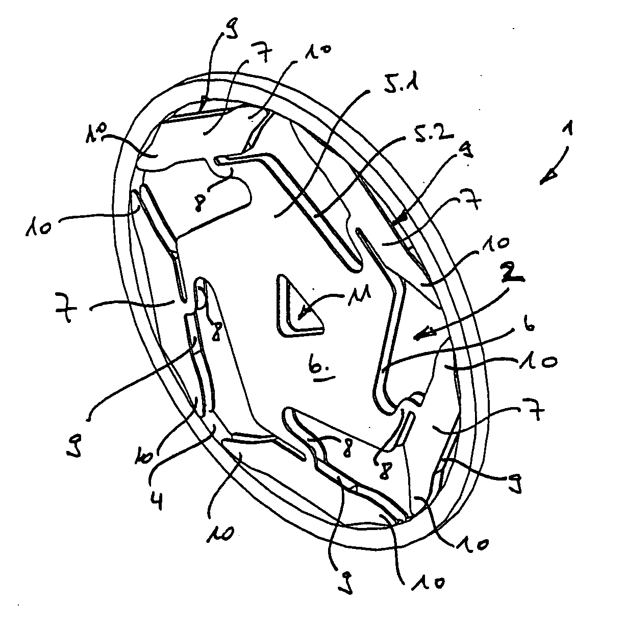
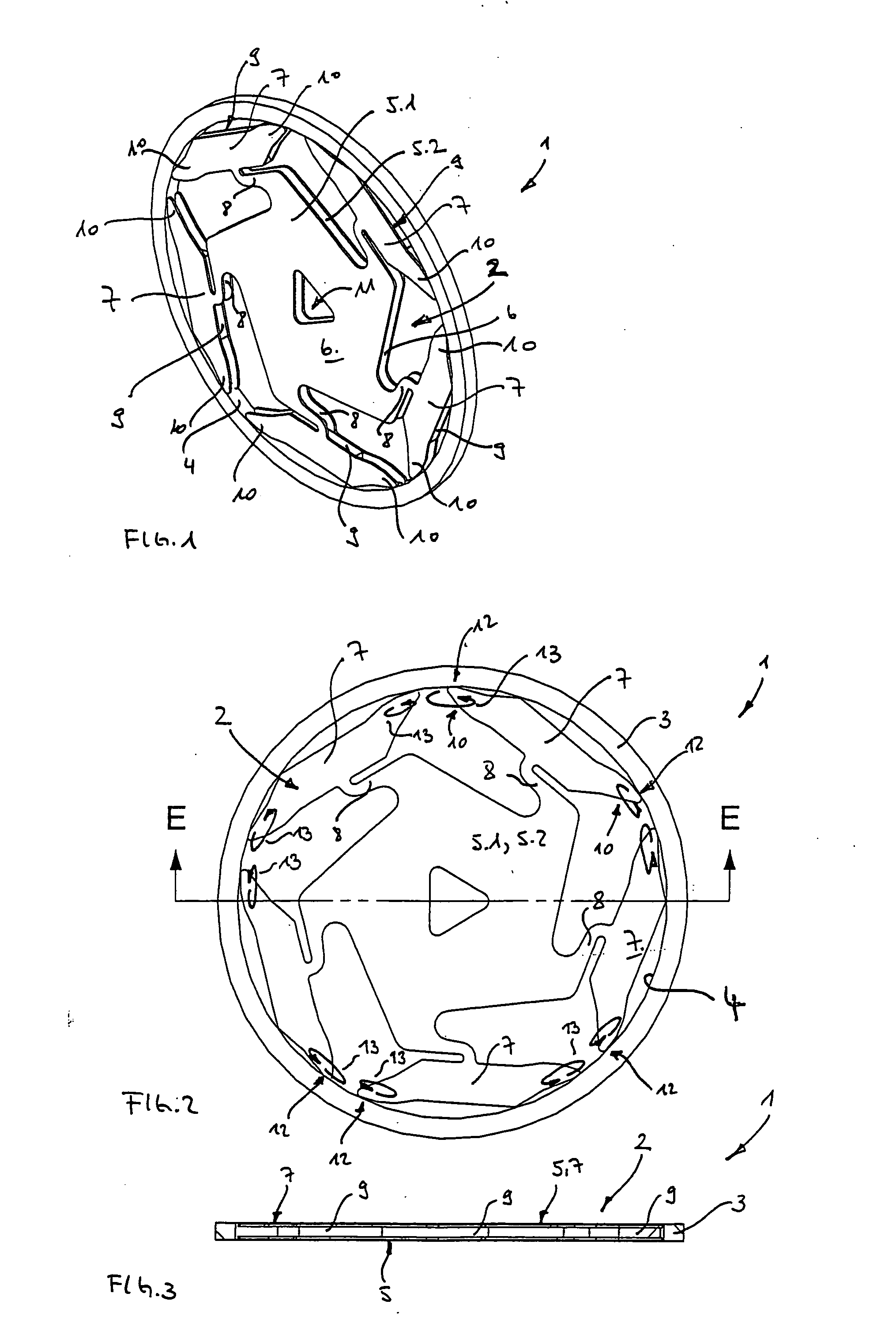
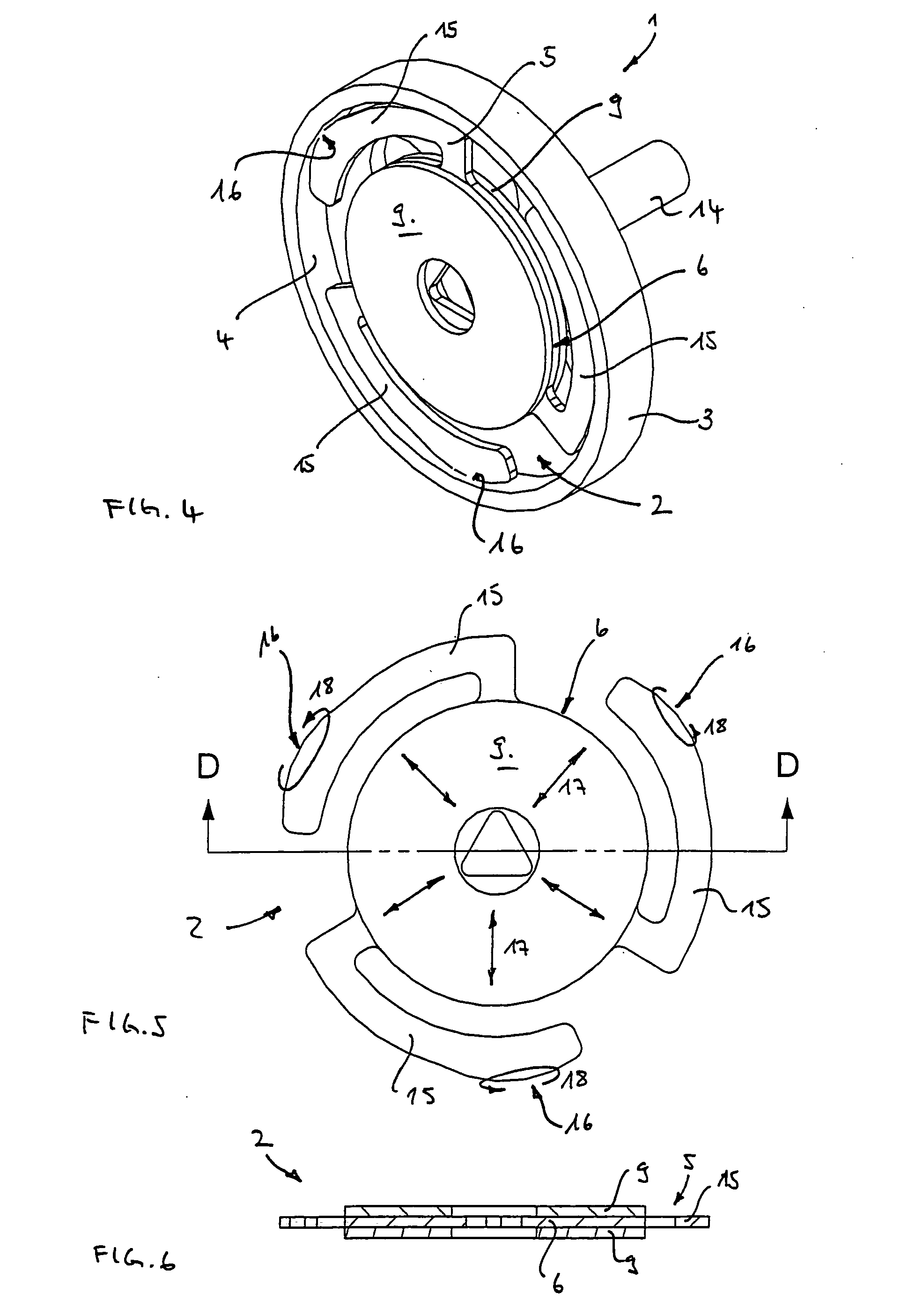
[0044]FIG. 1 shows a first embodiment of a drive 1 according to the invention. The drive 1 comprises an inner part 2 and an outer part 3 with a cylindrical drive surface 4. The inner part comprises two oscillation elements (oscillation plates) 5.1, 5.2, which are arranged distanced to one another. The oscillation plates 5.1, 5.2 are designed to be planar and each comprise a middle part 6 about which the five arms 7 are arranged. The arms 7 serve as resonator regions. The arms 7 comprise spring regions 8 that connect the arms 7 to the middle part. The spring regions 8 serve for mounting and holding the resonator regions 7 with respect to the middle part 6. With the shown embodiment, the middle part 6, the resonator regions 7 and the spring regions 8 of each oscillation element 5.1, 5.2 are manufactured of sheet metal e.g. by punching, or cutting with a laser beam.

[0045] Between two distanced resonator regions 7 there are arranged rectangular piezoelements 9 which are stuck onto the ...


PUM


Abstract

A piezoelectric drive (1) with an inner part (2) that is surrounded by an outer part (3). The inner part (2) includes at least one piezoelement (9) that is actively connected to an oscillation element (5). The oscillation element (5) has a middle part (6) about which at least one arm (7, 15) is arranged. The arm is actively connected to the outer part (3) via an interaction region (16) and is designed such that, when set into oscillation by way of the at least one piezoelement (9), it drives the outer part (3) relative to the inner part (2).

Description

BACKGROUND OF THE INVENTION [0001] The invention relates to a piezoelectric drive having an inner part and an outer part, wherein the inner part has a piezoelement and an oscillation element that cooperate to drive the outer part relative to the inner part. [0002] Piezoelectric drives, that is to say drives by way of piezoceramic materials which may be mechanically changed by an electrical voltage field are suitable in particular for miniaturized applications, for example for motors with a motor volume of a magnitude of a few cubic centimetres or even with a volume which is smaller than one cubic centimeter. Further advantages of these drives are a high moment at low speeds, a simple controllability, a smooth running, a relatively simple construction and their insensitivity with regard to external magnetic fields as well as the fact that they themselves produce no magnetic fields. [0003] Piezoelectric drives of the so-called standing-wave type as a driving element comprise at least ...

Claims


Application Information

Patent Timeline
Patent Type & Authority Applications(United States)
IPC IPC(8): H02N2/00H01L41/09H02N2/10
CPCH02N2/103H02N2/001
Inventor WITTEVEEN, BONNY
Owner MINISWYS
Why Eureka
Try Eureka