Eureka AIR delivers breakthrough ideas for toughest innovation challenges, trusted by R&D personnel around the world.

Surface light source device, method of manufacturing the same, backlight assembly and liquid crystal display apparatus having the same

a technology of liquid crystal display and surface light source, which is applied in the direction of discharge tube luminescnet screen, instruments, and applications of light source coatings, etc., can solve the problems of less brightness uniformity of ccfls, increase the size and weight of ccfls, and achieve the effect of improving the brightness and brightness uniformity of emitted light and reducing power consumption

Inactive Publication Date: 2005-01-13
SAMSUNG ELECTRONICS CO LTD
View PDF8 Cites 23 Cited by
  • Summary
  • Abstract
  • Description
  • Claims
  • Application Information

AI Technical Summary

Benefits of technology

[0007] The present invention provides a surface light source device capable of improving the brightness and brightness uniformity of emitted light with lower power consumption.
[0008] The present invention further provides a method for manufacturing the surface light source device, capable of improving the brightness and brightness uniformity of emitted light with lower power consumption.
[0009] The present invention still further provides a backlight assembly having the surface light source device and capable of lowering power consumption, generating the light having a uniformed brightness and decreasing manufacturing cost.
[0010] The present invention still further provides an LCD apparatus having the surface light source device and capable of lowering power consumption, generating the light having a uniformed brightness and decreasing manufacturing cost.

Problems solved by technology

However, since CCFLs have less brightness uniformity, LCD apparatuses employing CCFLs as the light supply part require an optical member such as a light guide plate (LGP), a diffusion member and a prism sheet or the like in order to supply the light of the uniform brightness, and become bigger and heavier.

Method used


Image

  • Surface light source device, method of manufacturing the same, backlight assembly and liquid crystal display apparatus having the same
  • Surface light source device, method of manufacturing the same, backlight assembly and liquid crystal display apparatus having the same
  • Surface light source device, method of manufacturing the same, backlight assembly and liquid crystal display apparatus having the same

Examples


Embodiment Construction

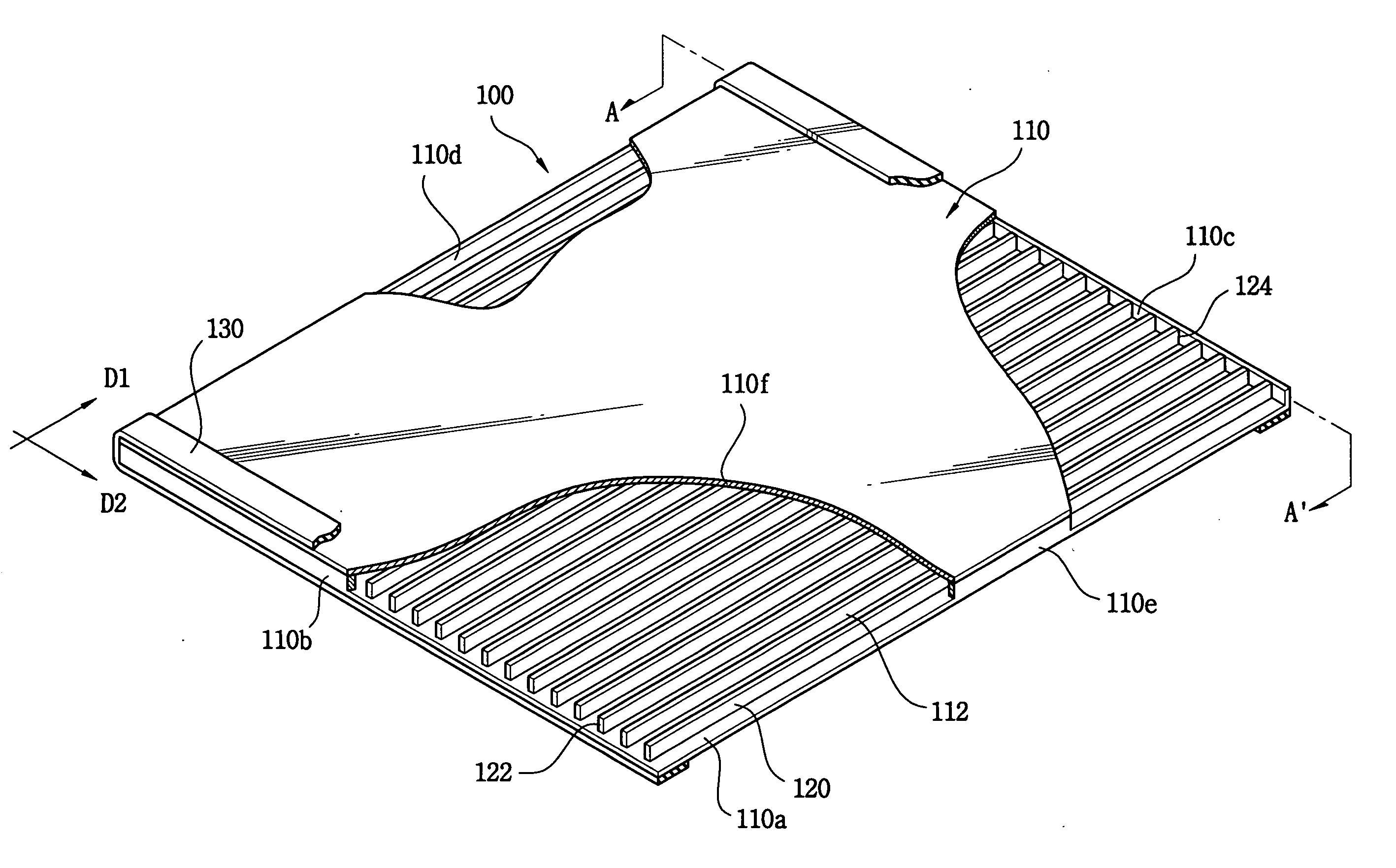
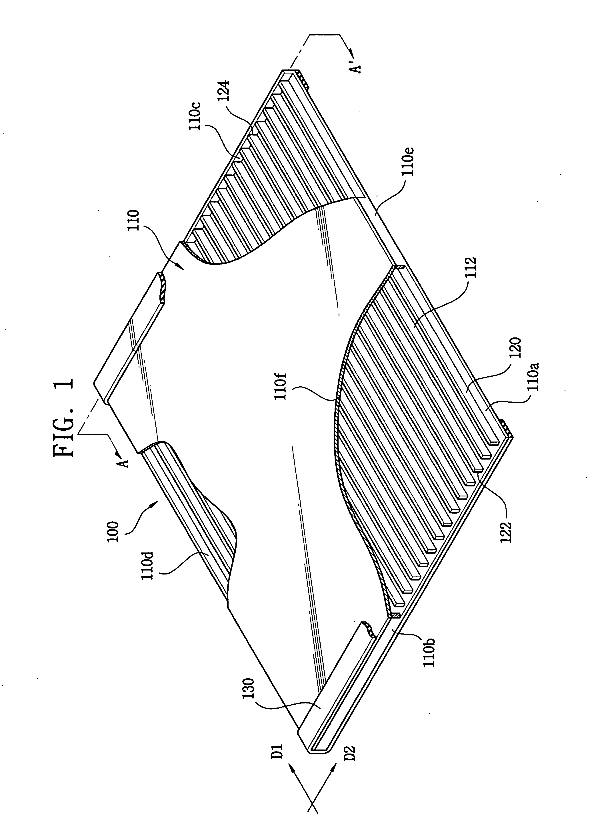
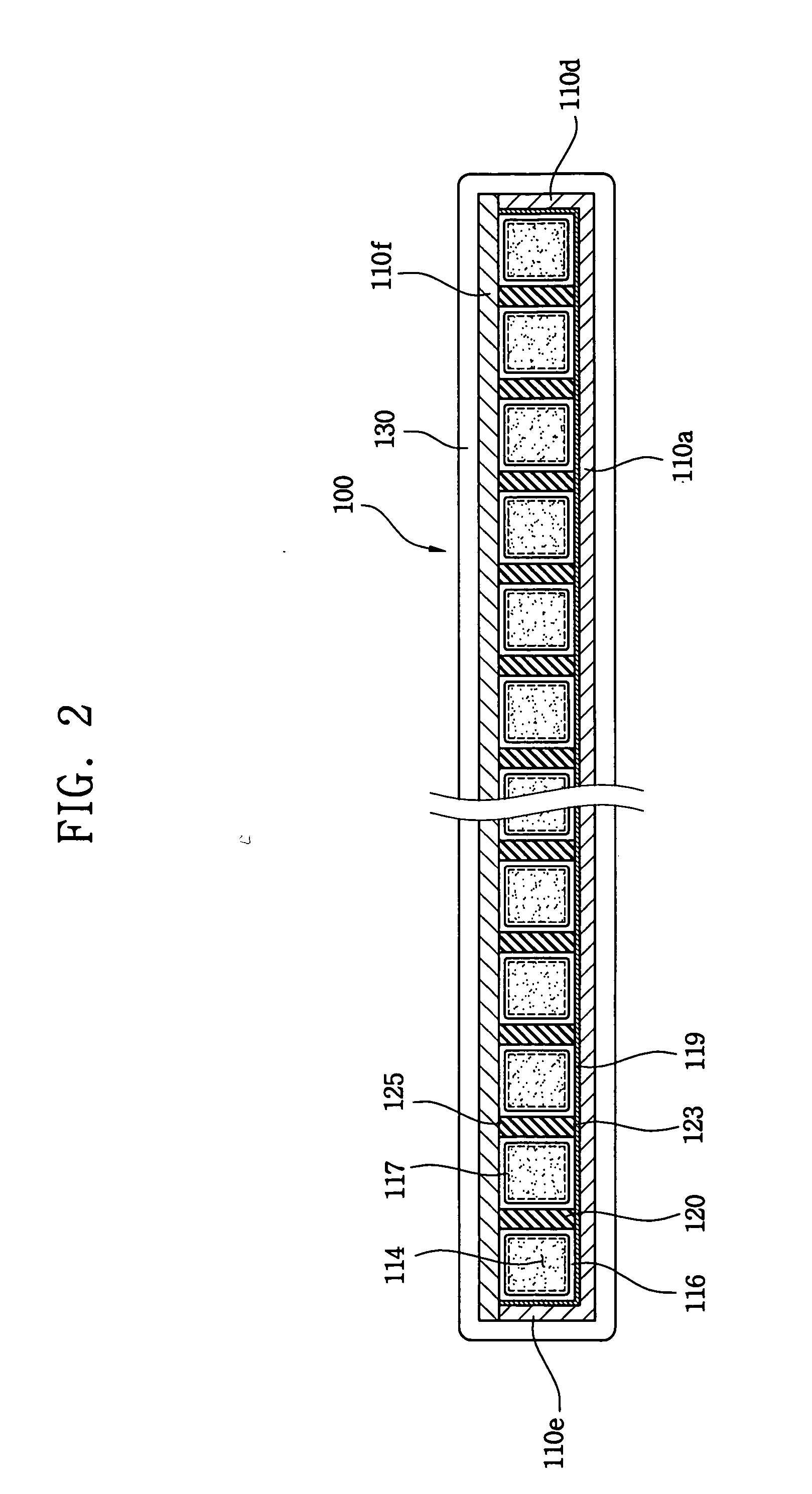
[0060]FIG. 1 is a perspective view showing a surface light source device according to an exemplary embodiment of the present invention. FIG. 2 is a cross-sectional view taken along the line A-A′ of FIG. 1. Referring to FIGS. 1 and 2, a surface light source device 100 includes a light source body 110, at least one space-dividing wall 120 and a pair of discharge voltage applying parts 130.

[0061] The light source body 110 includes a bottom surface 110a, first, second, third and fourth sidewalls 110b, 110c, 110d and 110e, a light exit surface 110f, at least two fluorescent layers 116 and a light reflection layer 119. The bottom surface 110a includes a flat and substantially rectangular shape. The first, second, third and fourth sidewalls 110b, 110c, 110d and 110e are substantially perpendicular to the bottom surface 110a, and the sidewalls 110b-110e and the bottom surface 110a form a flat receiving space 112 in the light source body 110 together. The sidewalls 110b-110e each have, for ...


PUM


Abstract

A surface light source device capable of emitting the light having uniform brightness with lower power consumption is provided. The surface light source device includes a light source body and at least one discharge voltage applying part. The light source body includes a bottom plate; a top plate which is disposed over the bottom plate to form a flat receiving space between the bottom plate and the top plate, the flat receiving space receiving discharge gas; and at least one space-dividing wall which is disposed on the bottom plate and divides the flat receiving space into at least two discharge spaces. The discharge voltage applying part is disposed on an outer surface of the light source body and applies discharge voltage to the light source body.

Description

BACKGROUND OF INVENTION [0001] 1. Field of the Invention [0002] The present invention relates to a surface light source device, a method of manufacturing the same, a backlight assembly and a liquid crystal display (LCD) apparatus having the same, and more particularly, to a surface light source device capable of emitting the light having a uniform brightness with lower power consumption, a method of manufacturing the same, a backlight assembly and an LCD apparatus having the same. [0003] 2. Description of the Related Art [0004] Liquid crystals have physical properties of both solid and fluid, electrical properties of different arrangement in accordance with an electric field, and optical properties of different light transmittance in accordance with the arrangements. Liquid Crystal Display (LCD) apparatuses display images using the liquid crystals. Because LCD apparatuses have many advantages such as thinner, smaller, lower power consumption, higher resolution, etc., they are widely...

Claims


Application Information

Patent Timeline
IPC IPC(8): F21S2/00F21Y103/00G02F1/13357G02F1/1335H01J1/62H01J9/22H01J9/24H01J9/26H01J61/00H01J61/067H01J61/30H01J61/92H01J63/04H01J65/00H01J65/04
CPCH01J9/245H01J9/261H01J65/046H01J61/305H01J61/92H01J61/067G02F1/1335
Inventor KIM, HYOUNG-JOOJANG, HYEON-YONGBYUN, JIN-SEOBKIM, JOONG-HYUN
Owner SAMSUNG ELECTRONICS CO LTD
Why Eureka
Eureka Blog
Learn More