3-D imaging system

a 3d imaging and image processing technology, applied in the field of 3d imaging systems, can solve the problems of difficult to keep in synchronization, limited degree of resolution, expensive system, etc., and achieve the effect of facilitating the location of the object being scanned

Inactive Publication Date: 2005-01-13
UNIV OF SOUTH FLORIDA
View PDF18 Cites 33 Cited by
  • Summary
  • Abstract
  • Description
  • Claims
  • Application Information

AI Technical Summary

Problems solved by technology

These systems are adapted to generate information over a large scan area, but are limited in degrees of resolution, which dictates accuracy of the information, based on the ping rates and distance to the object.
This system, however, requires a highly sophisticated interfacing of the actual signals and signal generators to provide the sought information, thus making it a very expensive system and one that, by virtue of the amount of variables to be controlled, may be difficult to keep in synchronization.
This again may be a highly expensive and complicated system to use.
This system, although being lower in cost and easier to use than the multi-platform systems, admittedly produces notable false readings.
An additional patent to Haley et al, U.S. Pat. No. 5,612,928, also describes a pixel classifying system, but again this system is incapable of producing 3-D images of photo quality, but instead resemble computer renderings.
This system, since again it uses sonar for imaging, is limited in the degree of resolution available.
This device is also limited in that it requires a diver to operate the equipment.
No discussion is made on how the images are enhanced or obtained in sufficient clarity to produce accurate representations of the object under investigation.

Method used


Image

  • 3-D imaging system
  • 3-D imaging system
  • 3-D imaging system

Examples


Embodiment Construction

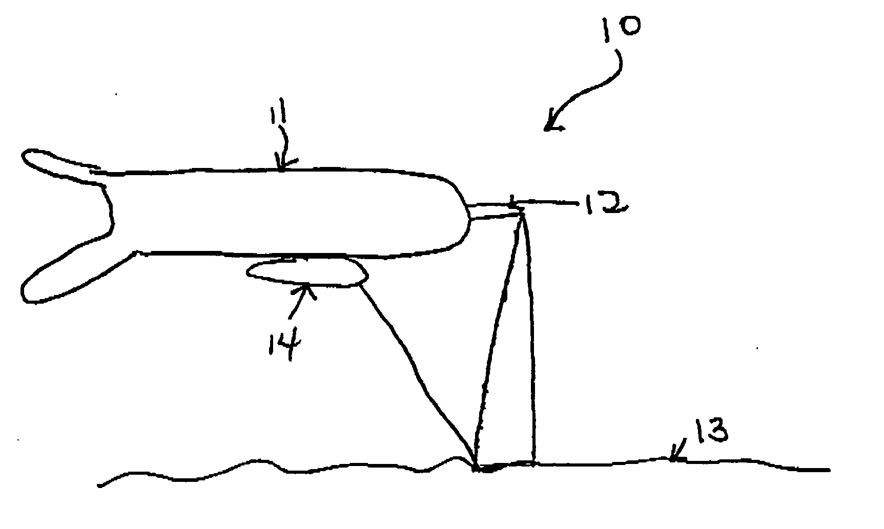
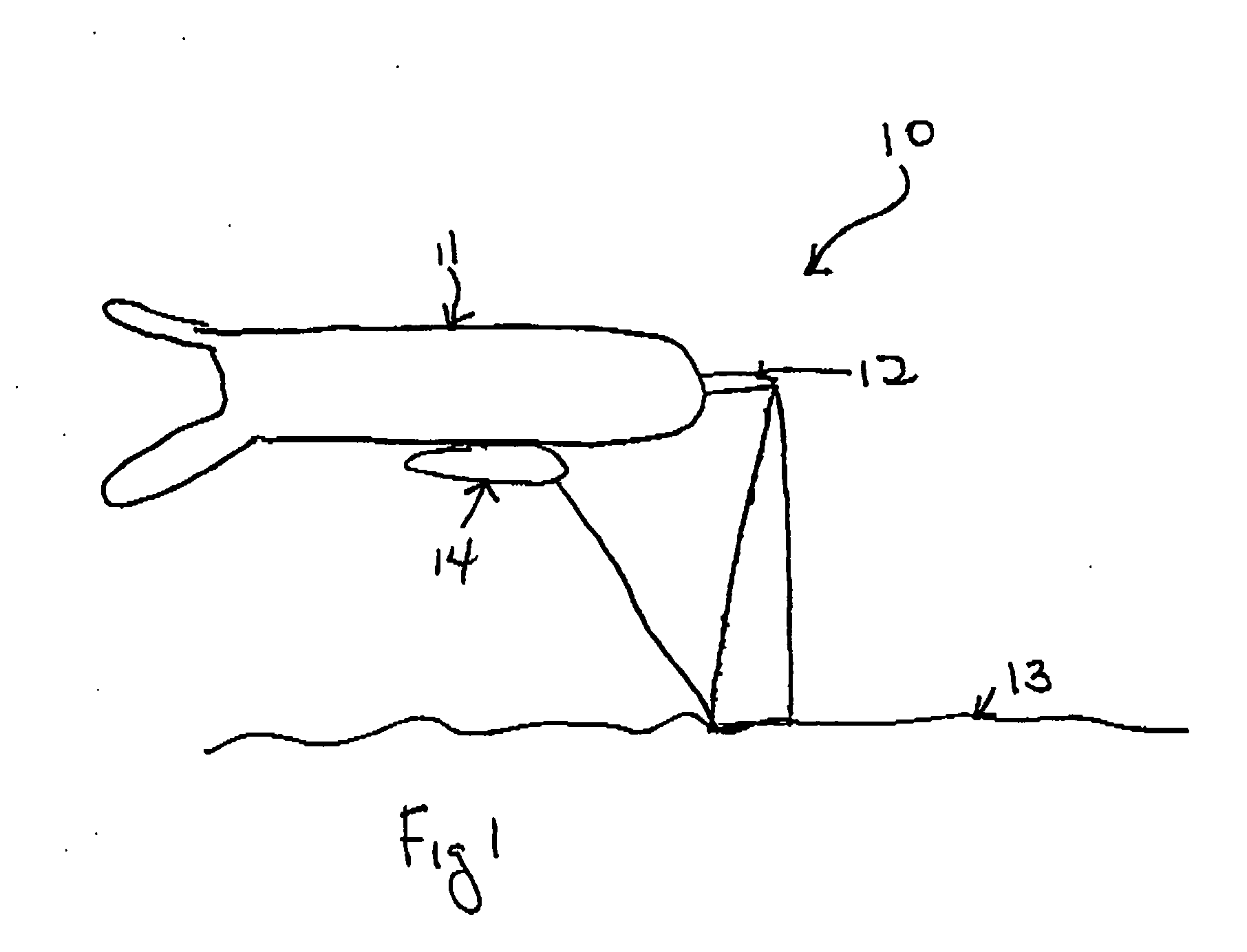
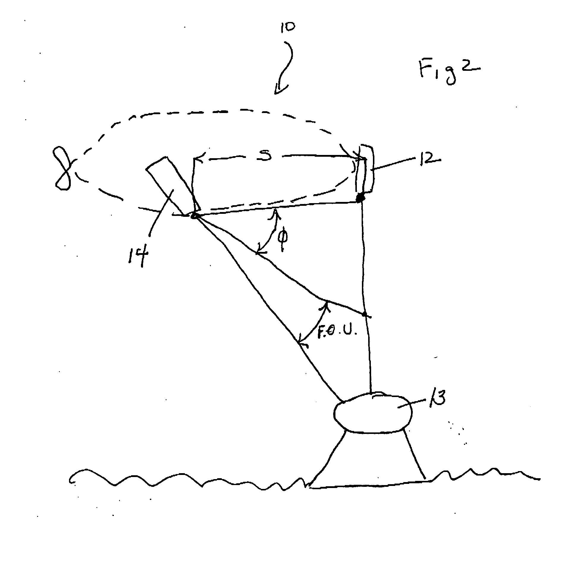
[0027] The present invention provides for a 3-D imaging system and method of obtaining 3-D images adapted for remote information acquisition. An embodiment of the present invention comprises a platform for supporting and conveying the imaging system, an illumination source affixed to the platform which transmits light to a subject surface, a light detector affixed to the platform adapted to collect light reflected back from the subject surface, and a data processing system in communication with the light detector for compiling data obtained from the reflected light to produce an image therefrom.

[0028] The present invention further provides for detecting the change in wavelength associated with light received from the subject surface. The illumination source for use with the present invention can be any light emitting device. It, however, is preferred in this invention to use a laser, and more preferably to use a laser with a planar geometry. The laser used by this invention can hav...


PUM


Abstract

The invention is directed to a remote 3-D imaging system which uses a novel illumination source to establish the relationship of the image features to the system, which is displayed by virtue of calculations. In addition to static surfaces, moving surfaces may be studied and corrections due to turbidity and platform position are also easily compensated for. The instant system may also contain a plurality of sensing systems based on light, including traditional reflective or elastic scattering and novel fluorescent or non-elastic scattering still and video imaging systems, including time-gated systems.

Description

CLAIM TO PRIORITY [0001] This applications claims priority to U.S. Provisional Application Ser. No. 60 / 320,076 filed on Apr. 1, 2003, and U.S. Provisional Patent Application Ser. No. 60 / 545,158 filed Feb. 17, 2004.STATEMENT OF GOVERNMENT INTEREST [0002] The work that led to this invention has been supported in part by a grant from the Office of Naval Research, Grant Number N00014-01-1-0279. Thus, the United States Government may have certain rights to this invention.FIELD OF THE INVENTION [0003] This invention relates to the field of imaging techniques and the in situ evaluation of the properties of surfaces or features of interest. More particularly, the instant invention relates to a system for inspecting the surface characteristics of a vessel or the ocean floor using a tethered or autonomous vessel designed to accurately image the surface under inspection to locate abnormalities or features of interest. BACKGROUND OF THE INVENTION [0004] Interest in the profile of underwater sur...

Claims


Application Information

Patent Timeline
Patent Type & Authority Applications(United States)
IPC IPC(8): H04N13/00
CPCH04N13/0253G01S17/023G01S17/107G01S7/4815G01S17/50G01S17/89G01S7/4802G01S17/48G01S17/18G01S17/86H04N13/254
Inventor KALTENBACHER, ERIC A.PATTEN, JAMES T.CARDER, KENDALL L.COSTELLO, DAVID K.KLOSKE, JOHN R.
Owner UNIV OF SOUTH FLORIDA
Why Eureka
Try Eureka