
Apparatus and method for generating wobble clock

a technology of wobble clock and apparatus, which is applied in the direction of generating/distributing signals, pulse techniques, instruments, etc., can solve the problems of complex delay circuit b>42/b>, difficult design and production, and large information storage capacity

Active Publication Date: 2005-01-13
TIAN HLDG
View PDF9 Cites 14 Cited by
  • Summary
  • Abstract
  • Description
  • Claims
  • Application Information

AI Technical Summary

Benefits of technology

[0017] Regardless of the variance of the phase-modulated wobble signal, the present invention wobble clock generating circuit is capable of dynamically generating a needed non-phase-modulated wobble signal according to the phase-modulated. Furthermore, the present invention wobble clock generating circuit is easy to be embodied. Therefore, the present invention wobble clock generating circuit costs only a few, and can be utilized in either DVD+R optical disc drive or DVD+RW optical disc drive.

Problems solved by technology

In present day information society, storage of large amounts of information has become a major problem.
However, as multimedia technology progresses increased storage requirements are required, and the storing capacity of a normal CD optical disc (650 MB) is becoming increasingly less satisfactory.
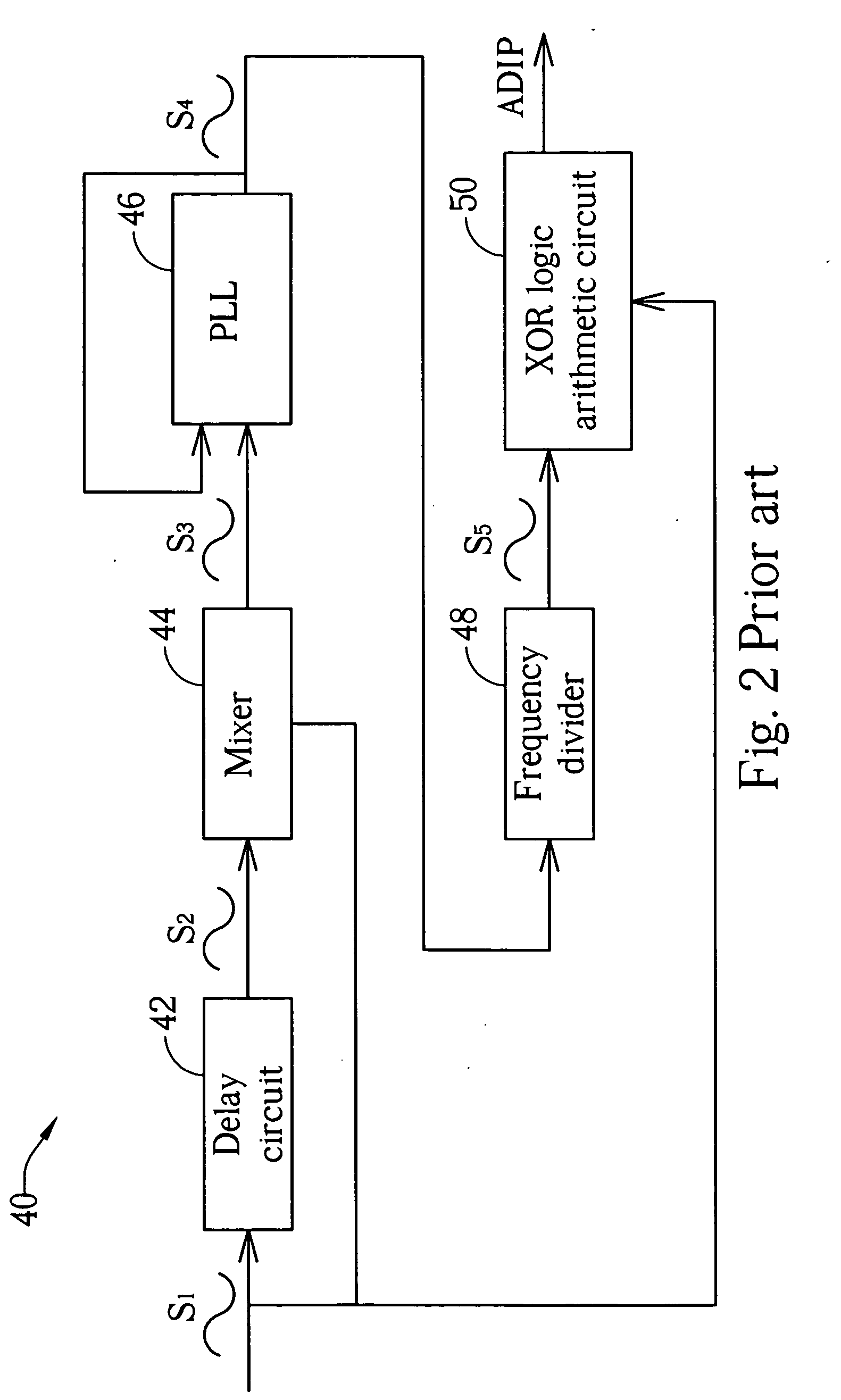
This in particular, makes the delay circuit 42 complicated and difficult to design and produce.

Method used


Image

  • Apparatus and method for generating wobble clock
  • Apparatus and method for generating wobble clock
  • Apparatus and method for generating wobble clock

Examples


Embodiment Construction

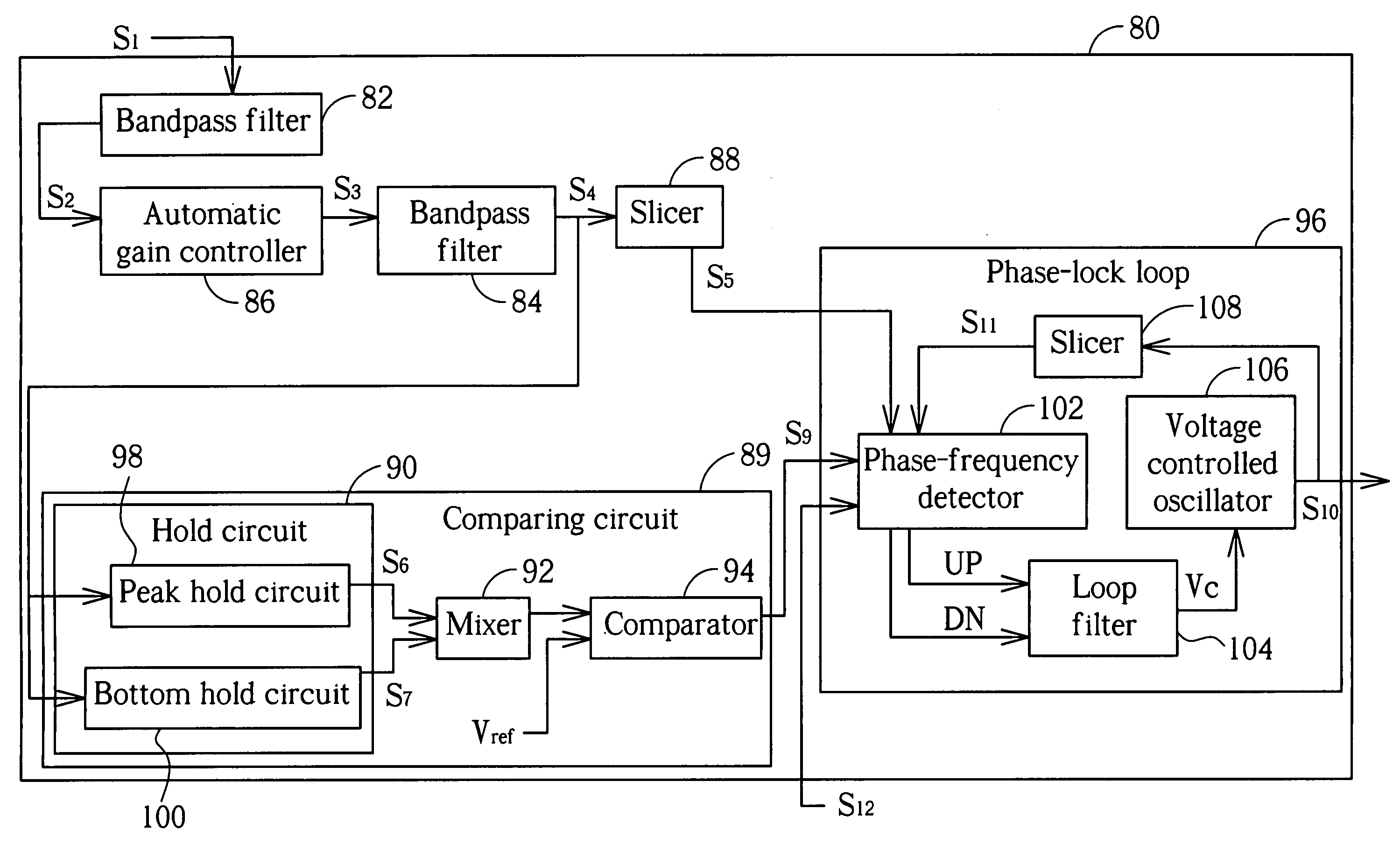
[0029] Please refer to FIG. 4, which is a block diagram of a wobble clock generating circuit 80 according to the present invention. The wobble clock generating circuit 80 comprises band-pass filters (BPF) 82 and 84, an automatic gain controller (AGC) 86, a slicer 88, a comparing circuit 89, and a PLL 96. Furthermore, the comparing circuit 89 comprises a hold circuit 90, a mixer 92, and a comparator 94. The hold circuit 90 comprises a peak hold circuit 98 and a bottom hold circuit 100. The PLL 96 comprises a phase-frequency detector (PFD) 102, a loop filter 104, a voltage-controlled oscillator (VCO) 106, and a slicer 108. The BPF 82 and 84 both have high Q factors and are used to filter out signals with frequencies that are in a predetermined frequency range. The BPF 82 is used to deal with wobble signal S1 read from a DVD+R optical disc or a DVD+RW optical disc and output a signal S2 to AGC 86. Note that the wobble signal S1 contains a wobble period of phase modulation for storing A...


PUM

PropertyMeasurementUnit
phaseaaaaaaaaaa
voltageaaaaaaaaaa
frequencyaaaaaaaaaa

Abstract

An apparatus for generating wobble clock comprises: a comparing circuit and a phase lock loop. The comparing circuit generates a combining signal according to peak values of the wobble signal and compares the output signal with a reference voltage to output a control signal. The phase lock loop drives the wobble clock to be synchronized with the wobble signal if the protection signal corresponds to a first logic level, and stops driving the wobble clock to be synchronized with the wobble signal if the protect signal corresponds to a second logic level.

Description

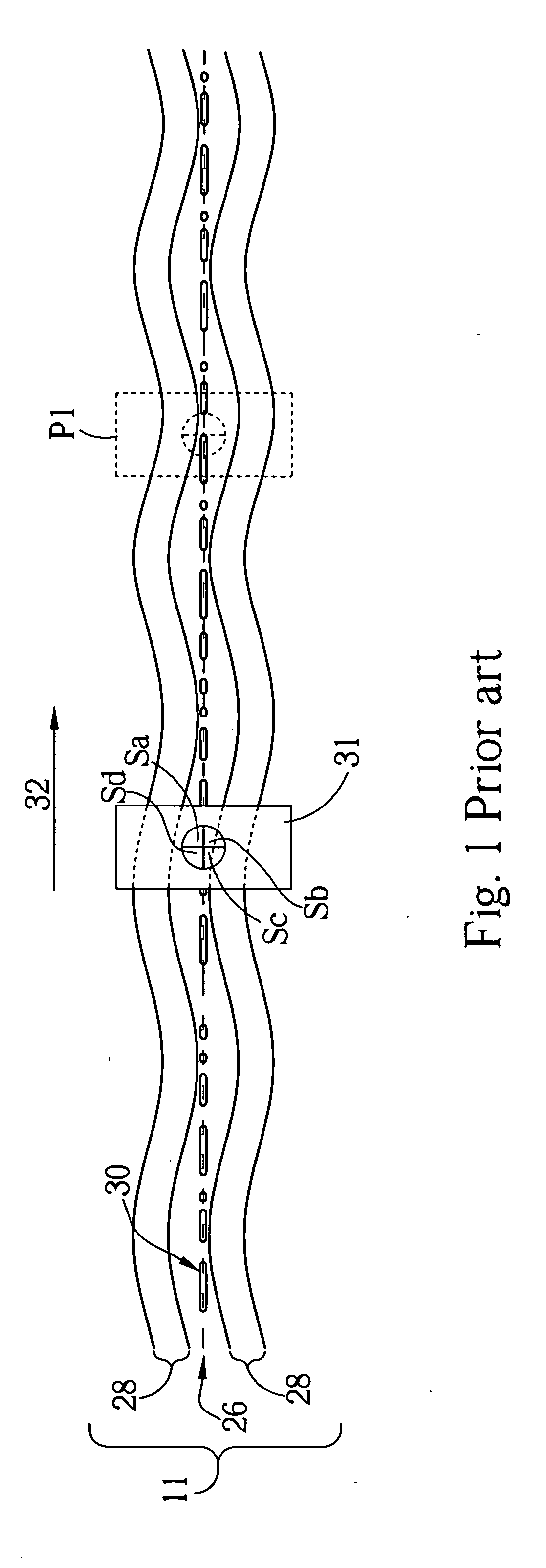
BACKGROUND OF INVENTION [0001] 1. Field of the Invention [0002] The invention relates to a wobble clock signal generating circuit of an optical disc drive, and more particularly, to a wobble clock signal generating circuit having both a controlling mechanism and the capability of generating a non-phase-modulated wobble clock signal according to a phase-modulated wobble signal. [0003] 2. Description of the Prior Art [0004] In present day information society, storage of large amounts of information has become a major problem. Of all types of storage medium, the optical disc is one of the most useful mediums because of its high storage capacity and small physical volume. However, as multimedia technology progresses increased storage requirements are required, and the storing capacity of a normal CD optical disc (650 MB) is becoming increasingly less satisfactory. Therefore, a new optical disc standard, the digital versatile disc (DVD), with increased storage capacity, has emerged. The ...

Claims


Application Information

Patent Timeline
Patent Type & Authority Applications(United States)
IPC IPC(8): G11B5/09G11B7/00G11B7/0045G11B7/095G11B7/1267G11B19/00G11B20/10G11B20/16G11B27/10G11B27/24H01H47/00H03D3/24H03D13/00H03L7/00H03L7/06H03L7/08H03L7/089H03L7/16H04B3/46
CPCG11B7/0945G11B7/0956H03L7/08G11B27/24G11B7/1267
Inventor HSIAO, YUAN-KUN
Owner TIAN HLDG
Learn More