Dynamic regulation of power consumption of a high-speed communication system
a communication system and power consumption technology, applied in the direction of line transmission details, error prevention, power distribution line transmission, etc., can solve the problems of increasing the relative degree of power consumption of the circuit, affecting the reliability of the system, and extending the design cycle, so as to reduce the power consumption
- Summary
- Abstract
- Description
- Claims
- Application Information
AI Technical Summary
Benefits of technology
Problems solved by technology
Method used
Image
Examples
first embodiment
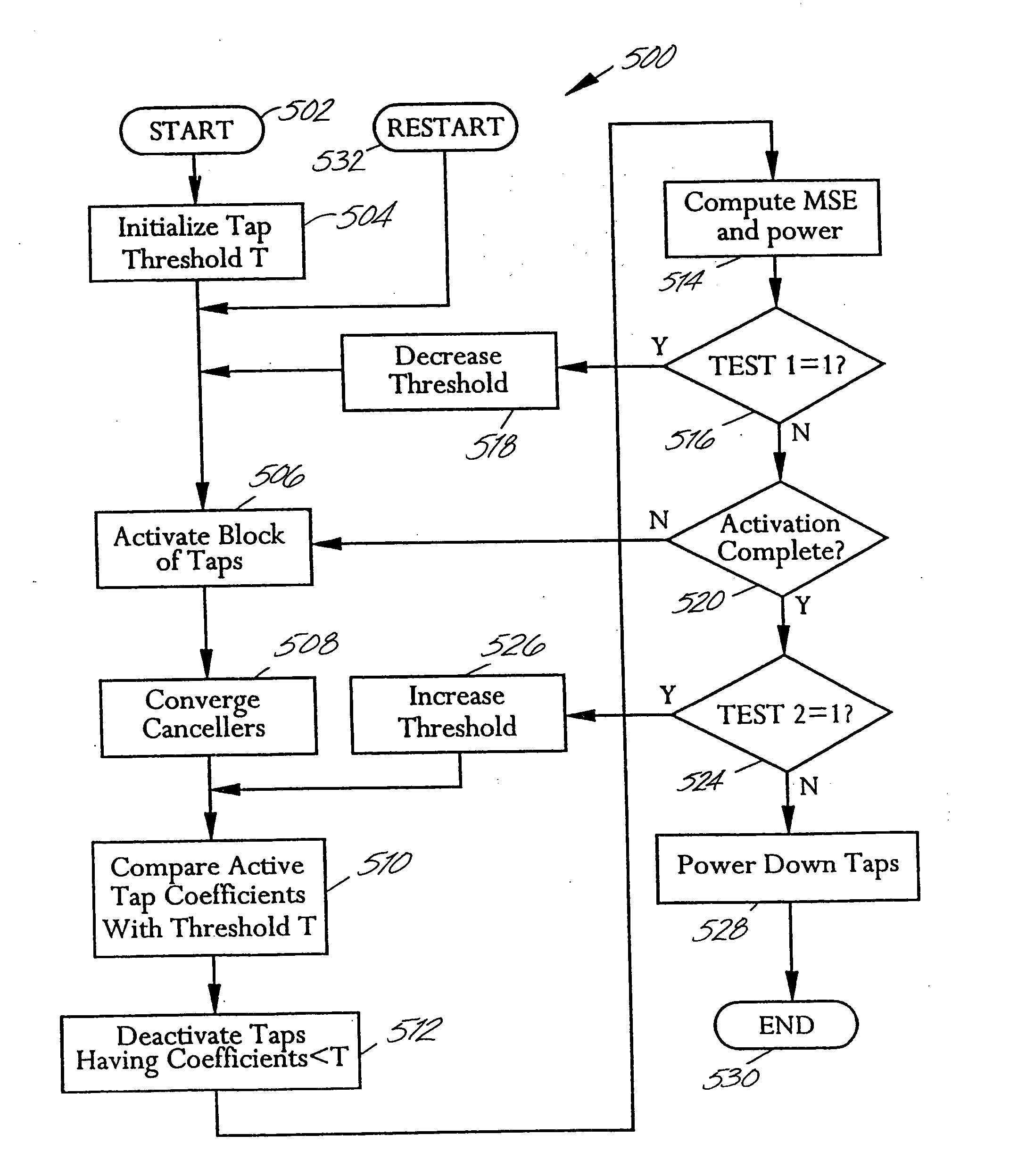
The absolute values of the active tap coefficients are compared with the threshold (block 510). The taps whose absolute values are less than the threshold are deactivated (block 512). An error metric, typically a mean squared error (MSE) corresponding to a ratio of mean squared error to signal, and a power metric are computed (block 514). Process 500 then checks whether a first test is satisfied (block 516). In the invention, this first test is satisfied when the error metric is greater than the specified error and the power metric is smaller than the specified maximum power. If the error metric is greater than the specified error, this implies that the threshold has been set too high, causing too many taps to be deactivated, and this has degraded the system performance by more than the specified amount. If the first test is satisfied, then the threshold is decreased (block 518), and all the taps in the block being considered are activated again (block 506) and process 500 proceeds ...
third embodiment
In the present invention, the first few taps of each filter, e.g., the first 10 taps, are exempt from deactivation in order to avoid possible degradations of the system performance in the presence of jitter. The effect of jitter on these few taps is as follows. There is usually a large slew rate in these first few taps. Due to this slew rate, their numerical values could change significantly if the sampling phase of the received signal changes. In the presence of jitter, the sampling phase of the received signal can change dynamically. Thus, if some of the first few taps were insignificant for the system performance, they could become significant as the sampling phase changes. For this third embodiment, the flowchart of the deactivation process of block 512 is slightly different from the one shown in FIG. 6. The only modification to the flowchart of FIG. 6 is to equate, in block 606, the address to K instead of 0, where K+1 is the number of the first few taps exempt from deactivatio...
fourth embodiment
the present invention uses, as the error metric, the change in the true MSE instead of the true MSE. In other words, the value of {new (true MSE)−old (true MSE)} is computed and used as the error metric. In the fourth embodiment, the first test in block 516 is satisfied if the change in the true MSE is greater than a specified change value (e.g., a value that corresponds to a noise to signal ratio (NSR) change of 1 dB) and the power metric is smaller than the specified maximum power. The second test in block 524 is satisfied if the change in the true MSE is smaller than the specified change value or the power metric is greater than the specified maximum power. For example, if the true MSE is at a value corresponding to a NSR of −25 dB before the tap power regulating process is applied, and if the specified change value corresponds to a NSR change of 1 dB, then the final true MSE will be at a value corresponding a NSR of about −24 dB. This fourth embodiment can be used when there is ...
PUM
 Abstract
Description
Claims
Application Information
 - R&D
- Intellectual Property
- Life Sciences
- Materials
- Tech Scout
- Unparalleled Data Quality
- Higher Quality Content
- 60% Fewer Hallucinations
Browse by: Latest US Patents, China's latest patents, Technical Efficacy Thesaurus, Application Domain, Technology Topic, Popular Technical Reports.
© 2025 PatSnap. All rights reserved.Legal|Privacy policy|Modern Slavery Act Transparency Statement|Sitemap|About US| Contact US: help@patsnap.com


