
Image expansion and display method, image expansion and display device, and program for image expansion and display

a technology of image expansion and display method, applied in the field of image expansion and display, to achieve the effect of expanding image, high-speed display, and large capacity

Inactive Publication Date: 2005-01-13
PANASONIC CORP
View PDF3 Cites 18 Cited by
  • Summary
  • Abstract
  • Description
  • Claims
  • Application Information

AI Technical Summary

Benefits of technology

[0008] In view of the above-described problems, it is therefore an object of the present invention to largely reduce a memory capacity required for processing in expanding and displaying a JPEG compressed image file.
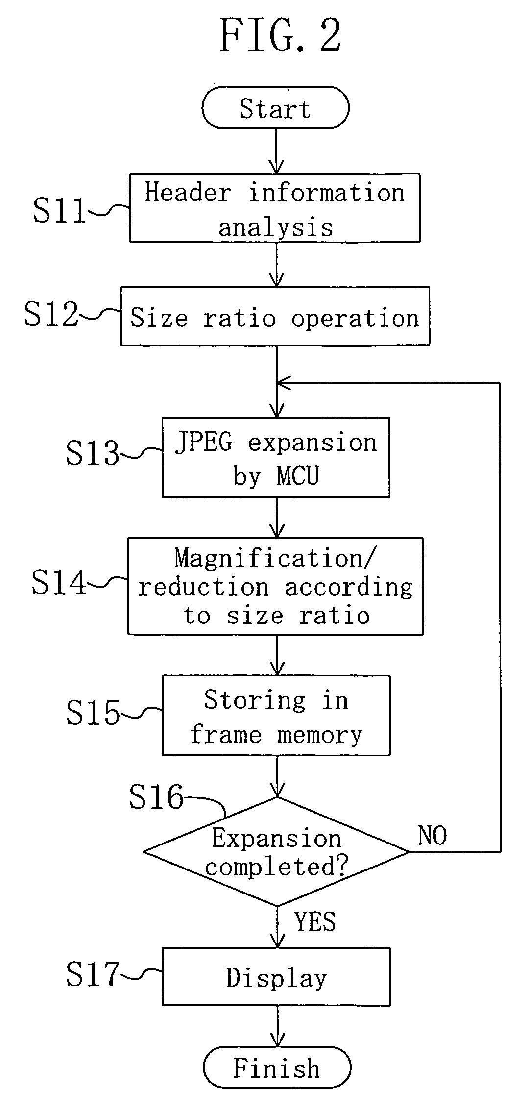
[0010] According to the present invention, image data is cut out and expanded from a JPEG compressed image file by MCU, and the expanded image data is magnified or reduced according to a size ratio corresponding to header information and properties of the display device and is directly accumulated in the display frame memory. Thus, when an image is expanded, a whole original image does not have to be stored. Accordingly, a frame memory for storing the whole image having a large capacity, which has been conventionally needed, is no longer necessary.
[0015] According to the present invention, a JPEG compressed image is not expanded and stored to a memory for each screen but is directly recorded by MCU in a display frame memory area. Thus, a memory having a large capacity, which has been conventionally needed, is no longer necessary. Moreover, storing to a memory is performed on a small scale, so that high speed display of an expanded image becomes possible.
[0016] Moreover, the present invention is particularly effective when a system of which the memory capacity can not be changed in a simple manner is formed. For example, when a memory is built in a system LSI with some other member, the present invention is particularly effective.

Problems solved by technology

This means that in an apparatus including a frame memory having a predetermined size, a compressed image file of which an original image size is larger than the predetermined size of the frame memory can not be expanded and displayed.

Method used


Image

  • Image expansion and display method, image expansion and display device, and program for image expansion and display
  • Image expansion and display method, image expansion and display device, and program for image expansion and display
  • Image expansion and display method, image expansion and display device, and program for image expansion and display

Examples


Embodiment Construction

[0021] Hereafter, embodiments of the present invention will be described with reference to the accompanying drawings.

[0022]FIG. 1 is a block diagram illustrating the configuration of an image expansion and display device according to an embodiment of the present invention. In FIG. 1, FL denotes an image file which is JPEG compressed and recorded on a recording medium and the like (which will be herein referred to as a “JPEG file”), 11 denotes a header information analysis section for analyzing header information of the JPEG file FL and reads an original image size while performing an operation of a size ratio with which a compression or expansion processing is performed, 12 denotes a JPEG expansion section for cutting out image data of the JPEG file FL and JPEG expanding the data, 13 denotes a resizing section for magnifying or reducing the image data expanded by the JPEG expansion section 12 according to the size ratio obtained by the header information analysis section 11, and 14...


PUM


Abstract

A header information analysis section analyzes header information of a compressed image file and reads an original image size while comparing the read original image size and an image size required for display and performing an operation of a size ratio. A JPEG expansion section expands image data of the image file by MCU. A resizing section magnifies or reduces by MCU the image data expanded by the JPEG expansion section according to the size ratio obtained by the header information analysis section and transfers the magnified or reduced data to a display frame memory.

Description

CROSS-REFERENCE TO RELATED APPLICATION [0001] This application claims priority under 35 U.S.C. §119(a) on Japanese Patent Application No. 2003-271770 filed on Jul. 8, 2003, the entire contents of which are hereby incorporated by reference. BACKGROUND OF THE INVENTION [0002] The present invention relates to an image expansion and display technique for expanding a JGEG compressed digital image data and outputting the data to a monitor built in a system or an external display device. [0003] In recent years, a wide range of image sizes for a small size image having a small capacity and a small angle of view, represented by a VGA size image, and a large size image having a large capacity and a large angle of view, reputed to have an increased number of pixels and high image quality accompanied with increase in the number of pixels of imaging devices, have been dealt with in the digital still camera industry, the camera-equipped cellular phone industry and like industry. That is, the rang...

Claims


Application Information

Patent Timeline
Patent Type & Authority Applications(United States)
IPC IPC(8): G06K9/32G06K9/36G06T3/40G09G5/00G09G5/36H04N1/32H04N1/387H04N1/393H04N1/41H04N5/225H04N5/93H04N7/46H04N101/00
CPCG06T3/40H04N1/32128H04N19/59H04N19/70H04N19/60H04N2201/3225H04N1/387
Inventor HACHIYAMA, HIROKITSUMURA, KEIICHITAKAHASHI, KENJI
Owner PANASONIC CORP
Learn More