

Image generation from plurality of images
- Summary
- Abstract
- Description
- Claims
- Application Information
AI Technical Summary
Benefits of technology
Problems solved by technology
Method used
Image

Examples
embodiment 1
A. Embodiment 1
[0051][0051] A-1. Device Arrangement:
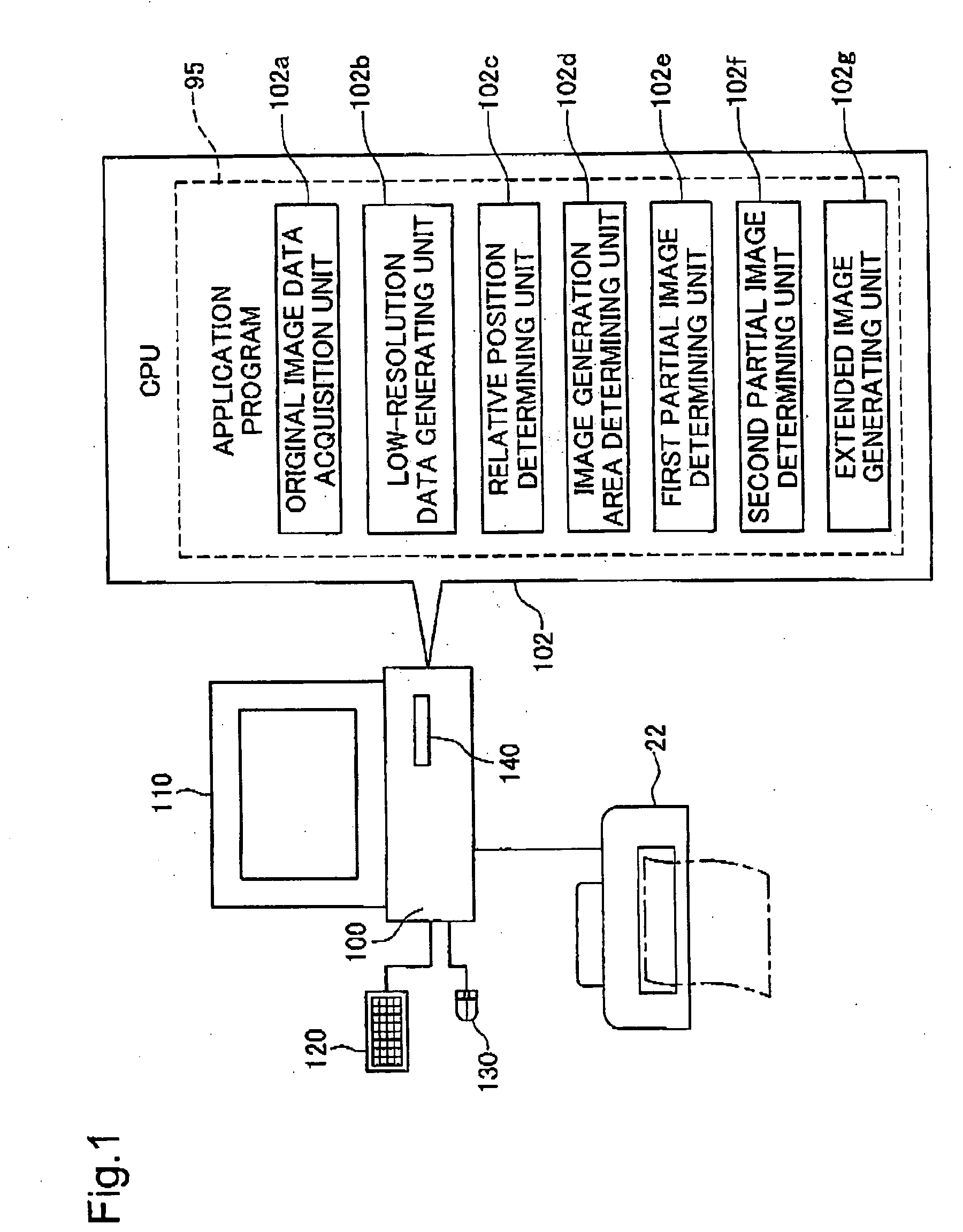
[0052]FIG. 1 illustrates a simplified arrangement of an image processing device as a embodiment of the invention. This image processing device comprises a personal computer 100 for performing predetermined image processing on image data; a keyboard 120, mouse 130 and CD-R / RW drive 140 as devices for inputting information to personal computer 100; and a display 110 and printer 22 as devices for outputting information. An application program 95 that operates on a predetermined operating system loaded onto computer 100. By running this application program 95, the CPU 102 of computer 100 realizes various functions.
[0053] When an application program 95 for performing image retouching or the like is run and user commands are input via the keyboard 120 or mouse 130, CPU 102 reads image data into memory from a CD-RW in the CD-R / RW drive 140. CPU 102 then performs predetermined image process on the image data, and displays the image on di...
embodiment 2
B. Embodiment 2
[0107] In Embodiment 1, a panorama image Fc is generated after first generating an entire converted partial image Ap2r from partial image Ap2. In Embodiment 2, however, rather than generating the entire converted partial image Ap2r in advance, when calculating tone values of pixels that make up panorama image Fc, tone values of pixels for the corresponding converted partial image are calculated at the same time, and the panorama image Fc is generated.
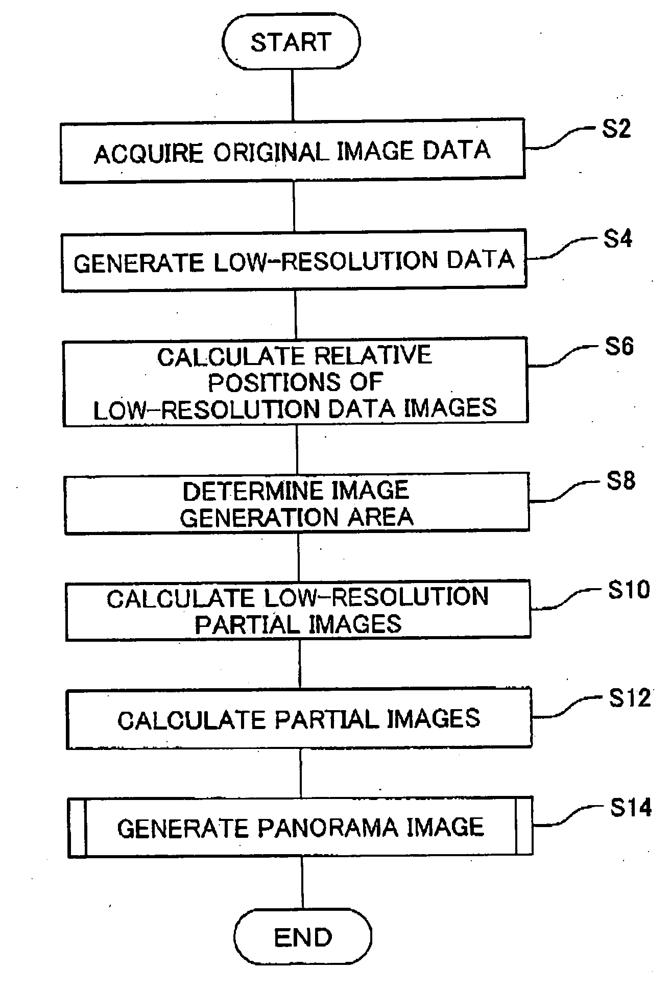
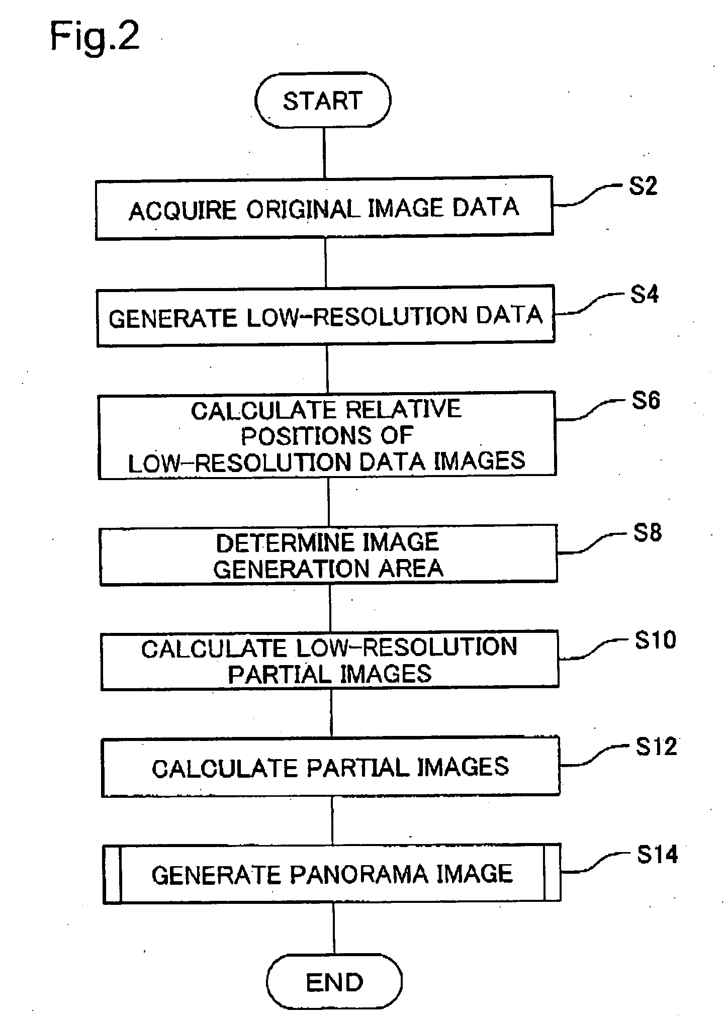
[0108]FIG. 11 is a flowchart showing a procedure for calculating tone values of pixels of panorama image Fc from tone values of pixels of partial images Ap1, Ap2. In Embodiment 2, when calculating tone values of pixels that make up panorama image Fc, in Step S72, there is first selected a target pixel for calculating tone value, from among the pixels that make up panorama image Fc.
[0109] In Step S74, a decision is made as to whether the target pixel is a pixel belonging to the left side area Fcp1, right side area Fcp2, ...
embodiment 3
C. Embodiment 3
[0114] Embodiment 3 differs from Embodiment 1 in terms of the relationship between original image data and panorama image data, and the number of original image data. In other respects, it is the same as Embodiment 1.
[0115]FIG. 12 illustrates a user interface screen displayed when determining an image generation area ALc on display 110 in Embodiment 3. In Embodiment 3, a single panorama image Fc is synthesized from original image data F3, F4, F5. Original image data F3, F4, F5 represent three sets of image data taken, while shifting the frame, of a landscape in which mountains Mt1-Mt4, ocean Sa, and sky Sk are visible.
[0116] In Embodiment 3, low-resolution data FL3, FL4, FL5 is generated from the original image data F3, F4, F5 in Step S4 of FIG. 2. Next, in Step S6, relative positions of the images represented by the low-resolution data FL3, FL4, FL5 are calculated. For example, relative positions of the low-resolution data FL3 image and the low-resolution data FL4 ...
PUM
 Abstract
Description
Claims
Application Information