
Organ manipulator apparatus

a manipulator and organ technology, applied in the field of organ manipulator apparatus, can solve the problems of inability to duplicate the function of inventive apparatus products, inability to design devices specifically designed for tissue stabilization to adapt to those motions, and inventive apparatus is not designed to stabilize specific areas of the organ to achieve the effect of preventing kinking

Inactive Publication Date: 2005-01-13
MAQUET CARDIOVASCULAR LLC
View PDF99 Cites 104 Cited by
  • Summary
  • Abstract
  • Description
  • Claims
  • Application Information

AI Technical Summary

Benefits of technology

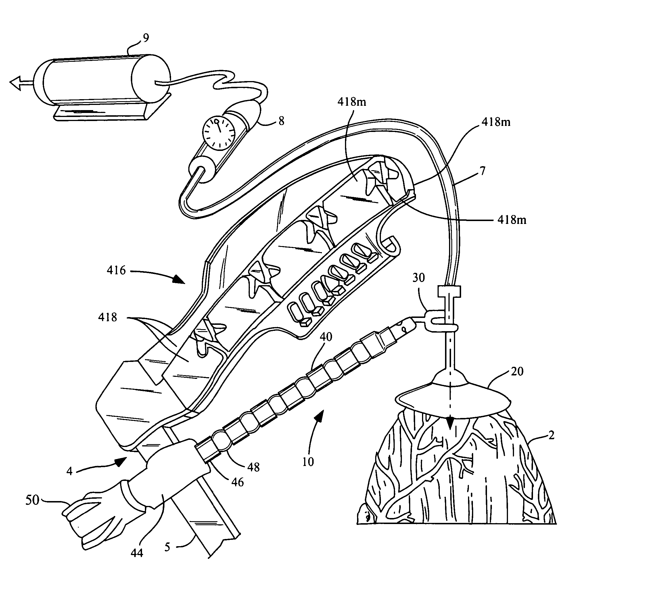
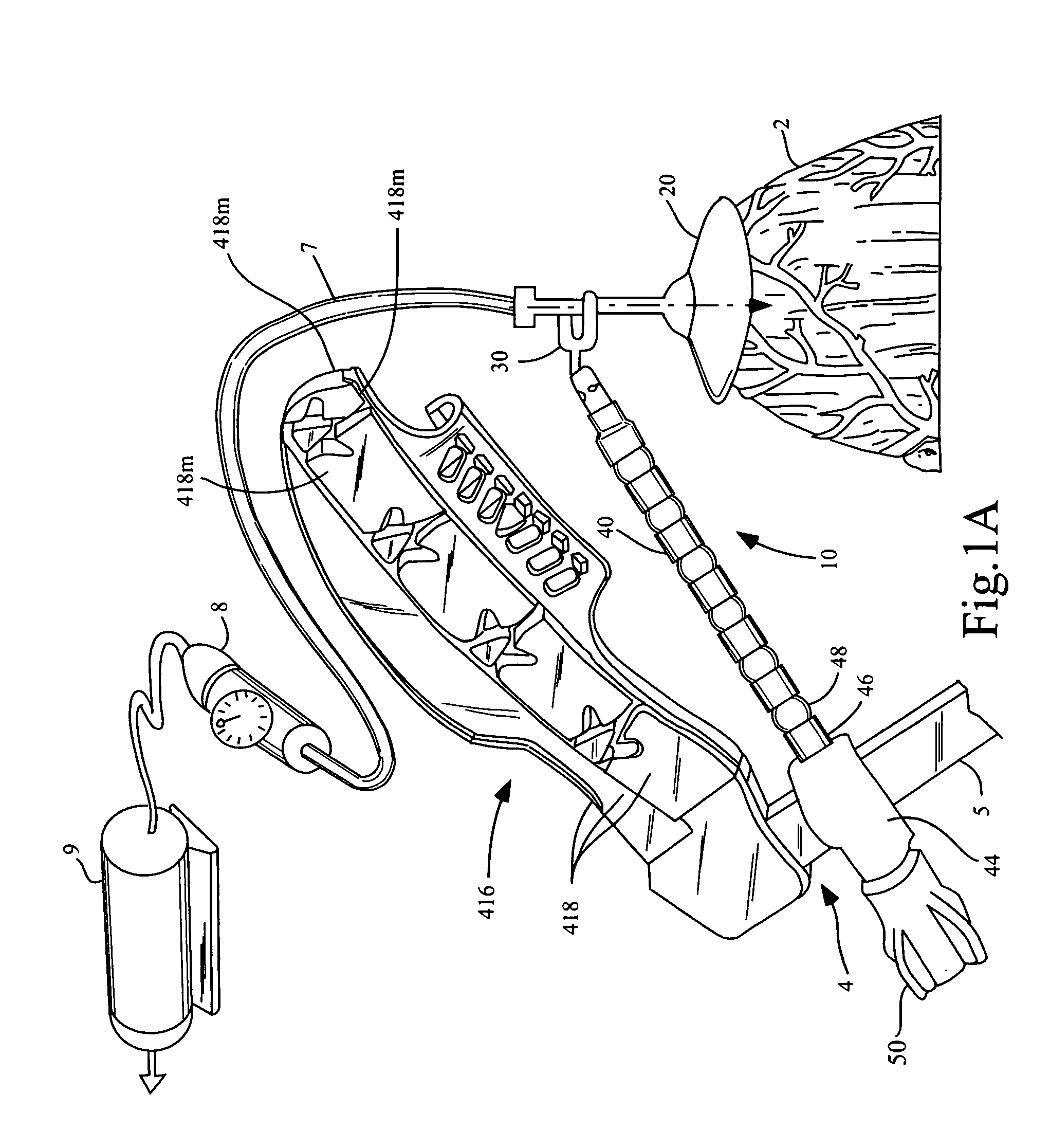
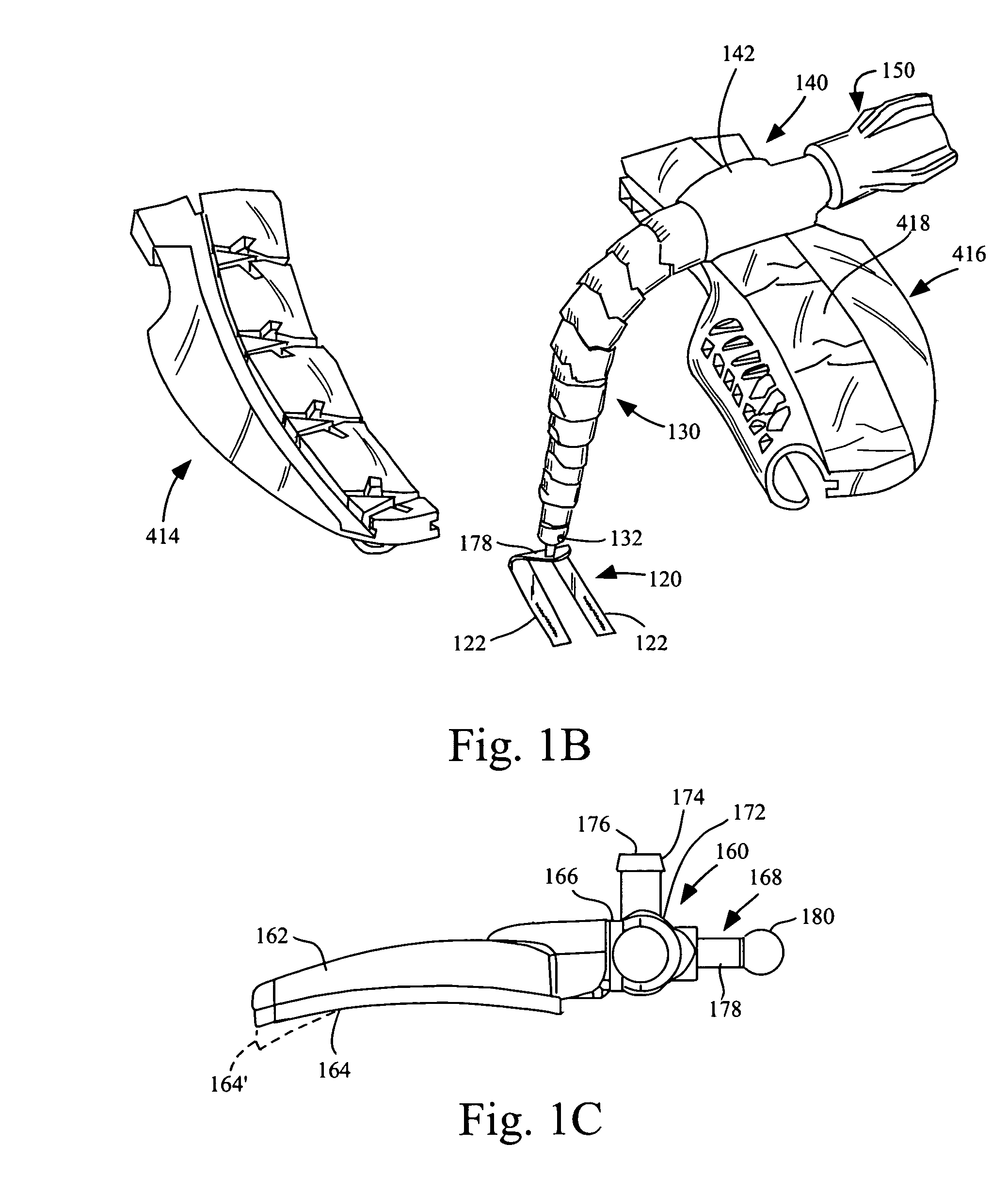
[0019] The apparatus of the invention differs in purpose and form from conventional tissue stabilization devices. The purpose of the inventive apparatus is to move an organ grossly from one position to another and maintain the organ in a desired gross position (without significantly constraining cardiac contraction and expansion or significantly effecting the contractility of the beating heart). The inventive apparatus is not designed to stabilize specific areas of the organ. The shape and nature of the suction member or members of the inventive apparatus differ from the suction cups of conventional tissue stabilization devices in the need to accommodate different anatomy. For example, the inventive suction member can be larger than a suction applicator of a conventional tissue stabilization device. Also, since the inventive apparatus exerts suction over a larger surface area of organ tissue, the required pressure differential can be less than that required by conventional tissue stabilization devices. The low-pressure differential has a clinical benefit in that the potential for creation of hematomas is lessened.
[0062] The suspension of the organ manipulator may further allow a limited amount of translation of the suction member, along an axis of the suction member, with respect to the support structure.

Problems solved by technology

However, such tissue stabilization products cannot duplicate the function of the inventive apparatus.
Devices designed specifically for tissue stabilization are not well suited to those motions.
The inventive apparatus is not designed to stabilize specific areas of the organ.

Method used


Image

  • Organ manipulator apparatus
  • Organ manipulator apparatus
  • Organ manipulator apparatus

Examples


Embodiment Construction

[0126] Before the present apparatus and methods are described, it is to be understood that this invention is not limited to particular structures described, as such may, of course, vary. It is also to be understood that the terminology used herein is for the purpose of describing particular embodiments only, and is not intended to be limiting, since the scope of the present invention will be limited only by the appended claims.

[0127] Where a range of values is provided, it is understood that each intervening value, to the tenth of the unit of the lower limit unless the context clearly dictates otherwise, between the upper and lower limits of that range is also specifically disclosed. Each smaller range between any stated value or intervening value in a stated range and any other stated or intervening value in that stated range is encompassed within the invention. The upper and lower limits of these smaller ranges may independently be included or excluded in the range, and each rang...


PUM


Abstract

Organ manipulation devices for atraumatically grasping the surface of an organ and repositioning the organ to allow access to a location on the organ that would otherwise be substantially inaccessible. Methods of accessing a beating heart, retracting the heart using an organ manipulation apparatus, and stabilizing a surgical target area with a stabilizer. Both the organ manipulator and stabilizer are fixed to a stationary object which may be a sternal retractor. A system for performing beating heart coronary artery bypass grafting includes a sternal retractor, organ manipulator and stabilizer.

Description

FIELD OF THE INVENTION [0001] The invention pertains to an apparatus for manipulating (and supporting in a retracted position) an organ such as a beating heart, methods of using the apparatus, a system including the apparatus and a stabilizer for stabilizing a select area of the beating heart, and optionally, a sternal retractor. The invention further pertains to method of using the apparatus for manipulating, as well as the systems. BACKGROUND OF THE INVENTION [0002] Coronary artery bypass grafting (CABG) has traditionally been performed with the use of a cardiopulmonary bypass (CPB) machine to oxygenate and perfuse the body during surgery. Recently, techniques have been developed to allow for performing CABG without the use of CPB by stabilizing the epicardial surface of a beating heart at the coronary anastomotic site with a stabilizer, by contacting the surface of the beating heart with the stabilizer to render a portion of the surface surrounding a target surgical site relative...

Claims


Application Information

Patent Timeline
Patent Type & Authority Applications(United States)
IPC IPC(8): A61B17/00A61B17/02A61B19/00
CPCA61B17/0206A61B19/26A61M1/0066A61B2017/0243A61B2019/267A61B2017/00243A61B90/57A61B90/50A61M1/80A61B17/30A61B2017/308
Inventor LAU, LIMINGLUNSFORD, JOHN P.
Owner MAQUET CARDIOVASCULAR LLC
Learn More