[0004] The object of the invention is to overcome the above mentioned shortcoming to provide an air-conditioner with both cooling and warming functions which is of novel structure, excellent performance, and low energy consume.
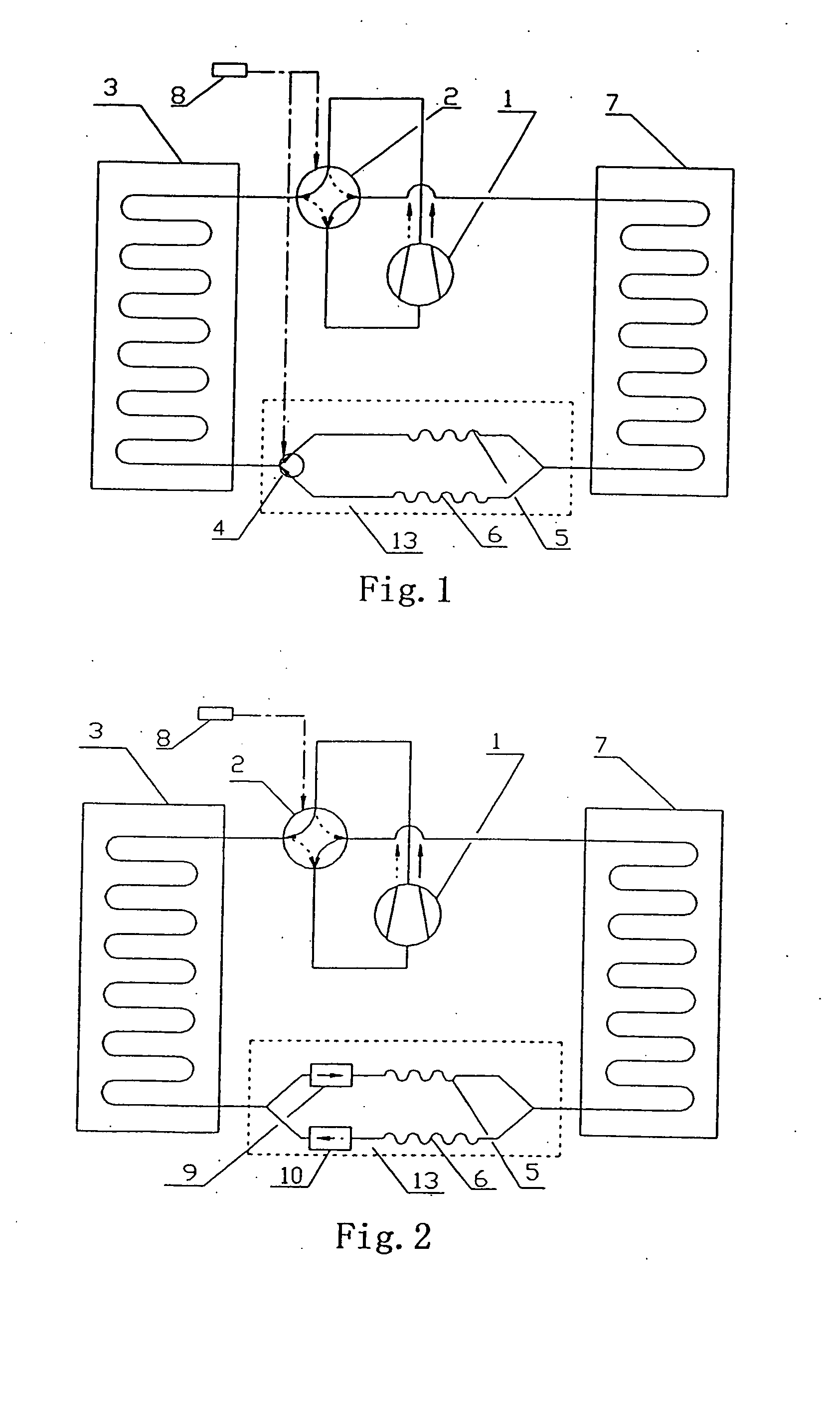
[0012] A combination formed by one or a group of capillary tube(s) and one or a group of expanding valve(s) in parallel, or a combination formed by parallel two groups formed by one or more capillary tube(s) and one or more expansion valve(s) connected in series has the features of both capillary and expanding valve, so as to act a coordinate effect and has more excellent performance. Moreover,
thermal engineering devices, such as gas-liquid separator, oil-liquid separator, could be connected in series between respective series capillary tubes or expanding valves. In cooling operation mode or warming operation mode, different combination of capillary tube and expanding valve could be selected to throttle according to adopted two-position three-way change over valve or one-way valve in different communication-obstruction condition respectively.
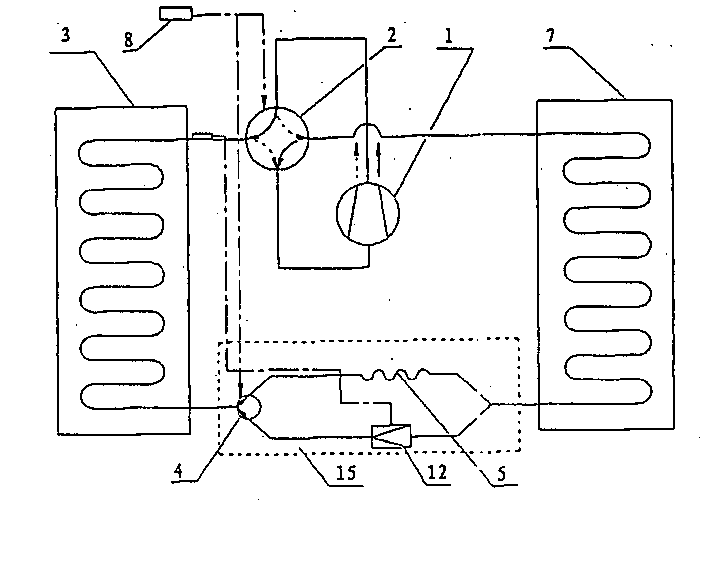
[0013] A novel air-conditioner with both cooling and warming functions according to the invention comprises a compressor, an out-door heat exchanger, an in-door heat exchanger and a four-way change-over valve, characterized in that it further comprises a parallel capillary device, a parallel expanding valve device or a combination of parallel capillary device and expanding valve, wherein the parallel capillary device, parallel the expanding valve device or the combination of parallel two groups of series capillary tube and expanding valve is connected respectively with the in-door and the out-door heat exchanger. Since the parallel capillary device, parallel the expanding valve device or the combination of parallel two groups of series capillary tube and expanding valve used in the air-conditioner with both cooling and warming functions according to the invention, under cooling operation mode and warming operation mode, one (or a group of) capillary tube(s), one (or a group of) expanding valve(s) or a combination of capillary tube and expanding valve is adopted individually to throttle, and the two (or two groups of) capillary tubes, the two (or two groups of) expanding valves or the combination of two capillary tubes and expanding valves connected in series work independently without interference each other. Therefore, the requirement of independent optimized design for cooling operation mode and warming operation mode of air-conditioner could be satisfied, so as to achieve the goal of excellent performance, reducing energy consume, increasing efficiency.
[0017] (2). The invention adopts the order of structural arrangement, that is under cooling operation mode, one-way valve is connected with out-door heat exchanger directly, i.e. one-way valve is placed at
high pressure side. The reason of this design arrangement is that since at
high pressure side (i.e.
refrigerant just flowing out of condenser is under high temperature and
high pressure liquid state), the temperature of
refrigerant is higher than the temperature of environment, and in this time
refrigerant is still in the condition of radiating outside. Under this condition, the temperature of gas-
liquid phase-change point of the cooling agent is higher, the role of core of one-way valve would not affect the flowing and phase-state of the refrigerant, and the stability of the state of refrigerant before entering capillary tube throttling is advantageous to raise efficiency of capillary throttling. On the contrary, if one-way valve is placed at downstream side of the throttling capillary, the state of refrigerant would be changed into
liquid state with low temperature and low pressure due to throttling of capillary, at this time the temperature of refrigerant is lower than the temperature of environment, i.e. in heat-absorbing state, in which state, due to low pressure of gas-phase, the refrigerant is easy to absorb heat to cause phase-change. Moreover, the one-way valve is located at outlet of the capillary tube, the disturbance of the core of one-way valve would intensify the alternation of the state of refrigerant, and the refrigerant would be vaporized in advance. Furthermore, the one-way valve is connected with in-door heat exchanger through longer connecting
pipe, so that the heat quantity absorbed by refrigerant enhances during flowing, the larger the absorbed heat quantity lowers the efficient utilization ratio of the refrigerant, and the phase-change of cooling agent in advance would enhance non-efficient loss of refrigerant, and would enhance the flowing resistance of refrigerant along path, thus reducing the work efficiency of the
system. To avoid such a condition, the one-way valve should be connected with the out-door heat exchanger first and then connected with the capillary tube.
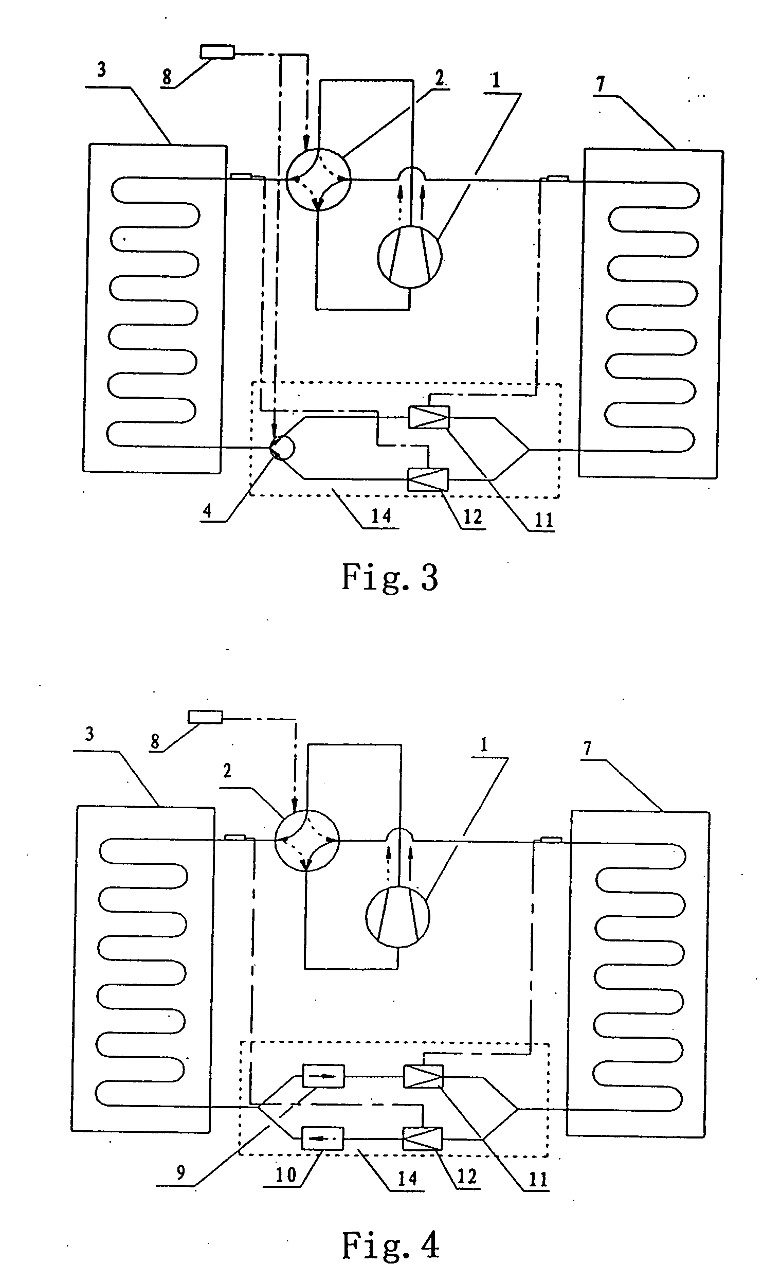
[0018] Under warming operation mode, one-way valve is placed at downstream side of the capillary tube and connected with out-door heat exchanger directly. The reason of this arrangement design is the different condition under warming operation mode, that is, warming operation mode always occurs at lower temperature of out-door of environment. Since lower temperature of the environment at warming operation mode, the thermal-conductive
temperature difference between the environment and the heat exchanger is smaller, the
heat flow density through the wall surface is lower, it is
disadvantage for heat exchanging of cooling agent, cooling agent would maintain one-way flowing condition and lower heat exchanging efficiency in a certain long flowing process, at this time,
disadvantage of smaller heat exchanging coefficient of single-phase flow could be changed by means of larger heat exchanging coefficient sufficiently of two-phase flow to expedite state of refrigerant from
liquid phase to be transformed to gas-
liquid phase, so as to raise
thermal conductivity of inner side of heat exchanger, thus increasing efficient utilization ratio of heat exchanger, which would benefit heat exchanging. Therefore one-way valve is placed at outlet of capillary tube and connected with out-door heat exchanger directly, the disturbance of core of one-way valve would intensify the alternation of the state of refrigerant, on the one hand, to expedite refrigerant from
liquid state to be changed to two-phase flow state, and on the other hand, by means of disturbance and mixture of one-way valve, to promote the even degree of refrigerant in
distributor, and to increase uniformity of split-flow of refrigerant, so as to increase utilization ratio of heat exchanger. In addition, the disturbance of one-way valve further benefit to expedite
vaporization and heat-absorption of refrigerant after throttling, and to expedite transform of refrigerant two-phase flow, so as to increase utilization ratio of out-door exchanger, and to enhance operational efficiency of the
system.
[0020] The invention provides a new generation cooling and warming air-conditioner having novel structure, excellent performance, low energy consume, high efficiency, and it can be applied to not only air-conditioner with both cooling and warming functions, but also other cooling equipment.

