Refrigeration cycle

a technology of refrigerating cycle and compressor, which is applied in the direction of machines/engines, positive displacement liquid engines, lighting and heating apparatus, etc., can solve the problems of increasing the cost of automotive air conditioners, difficult control of ejector cycle, and compressor capacity fluctuation, so as to reduce the cost of compressors

Inactive Publication Date: 2005-01-20
TGK
View PDF24 Cites 55 Cited by
  • Summary
  • Abstract
  • Description
  • Claims
  • Application Information

AI Technical Summary

Benefits of technology

[0009] The present invention has been made in view of the above described points, and an object thereof is to provide a refrigeration cycle for an automotive air conditioner reduced in the cost thereof.

Problems solved by technology

Particularly when the ejector cycle is applied to a refrigeration cycle for an automotive air conditioner, if the engine for driving an automotive vehicle is used as the drive source of the compressor, the rotational speed of the engine is largely dependent on operating conditions of the vehicle, causing fluctuation of the capacity of the compressor, which makes it difficult to control the ejector cycle.
Further, the ejector cycle has a large number of control valves and complicated piping, which increases the cost of the automotive air conditioner.

Method used


Image

  • Refrigeration cycle
  • Refrigeration cycle
  • Refrigeration cycle

Examples


Embodiment Construction

[0026] Hereinafter, embodiments of the present invention will be described in detail with reference to the drawings.

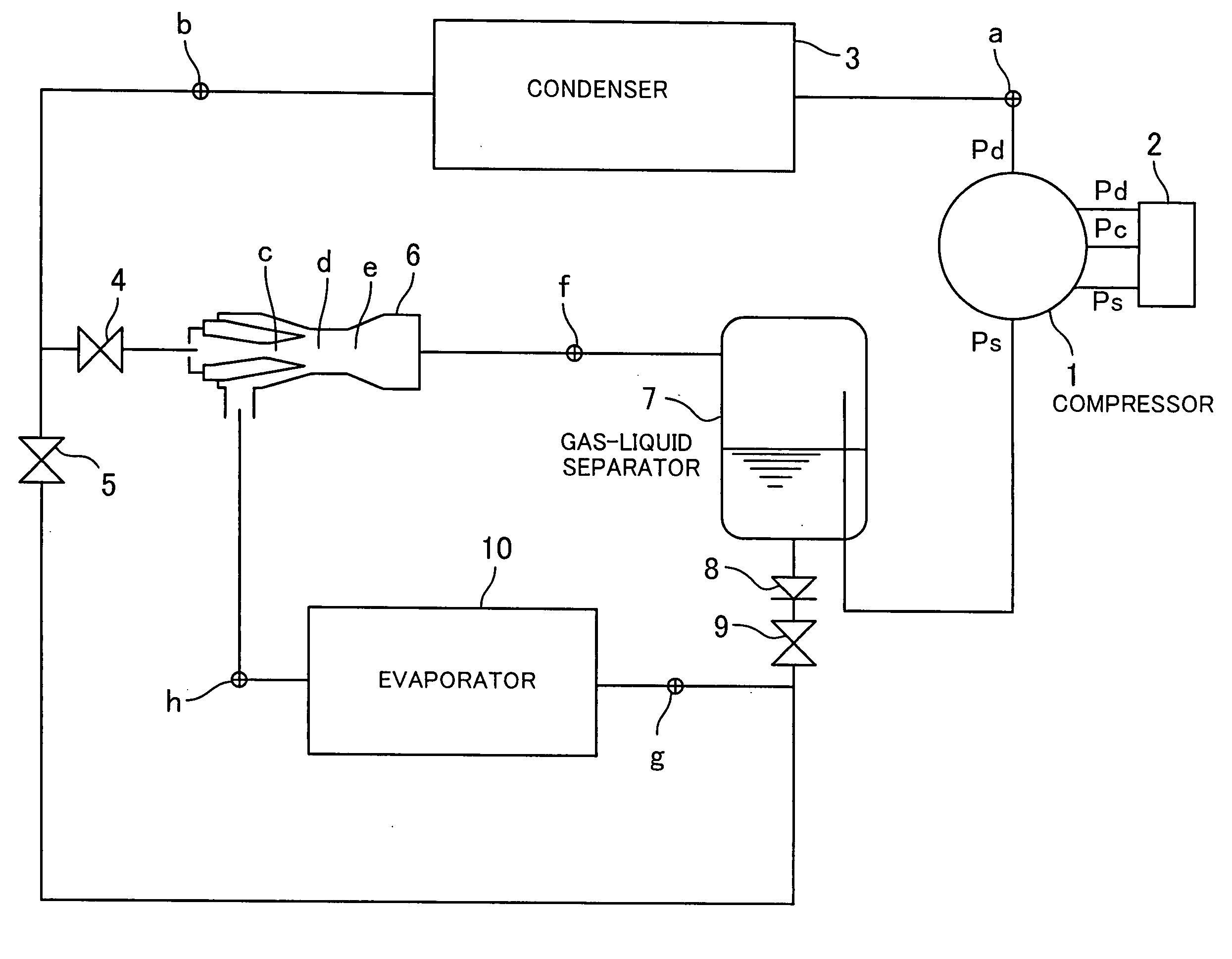
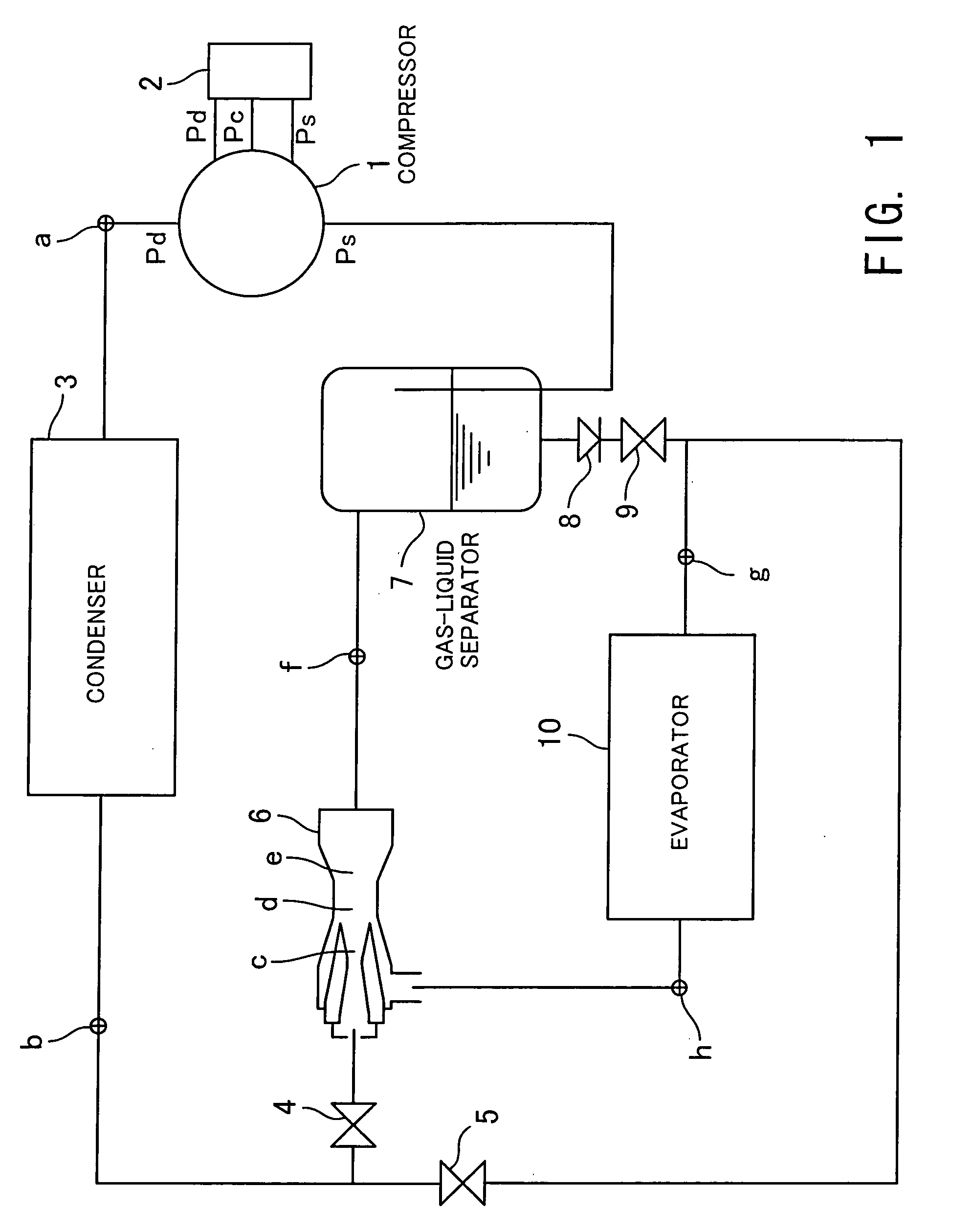
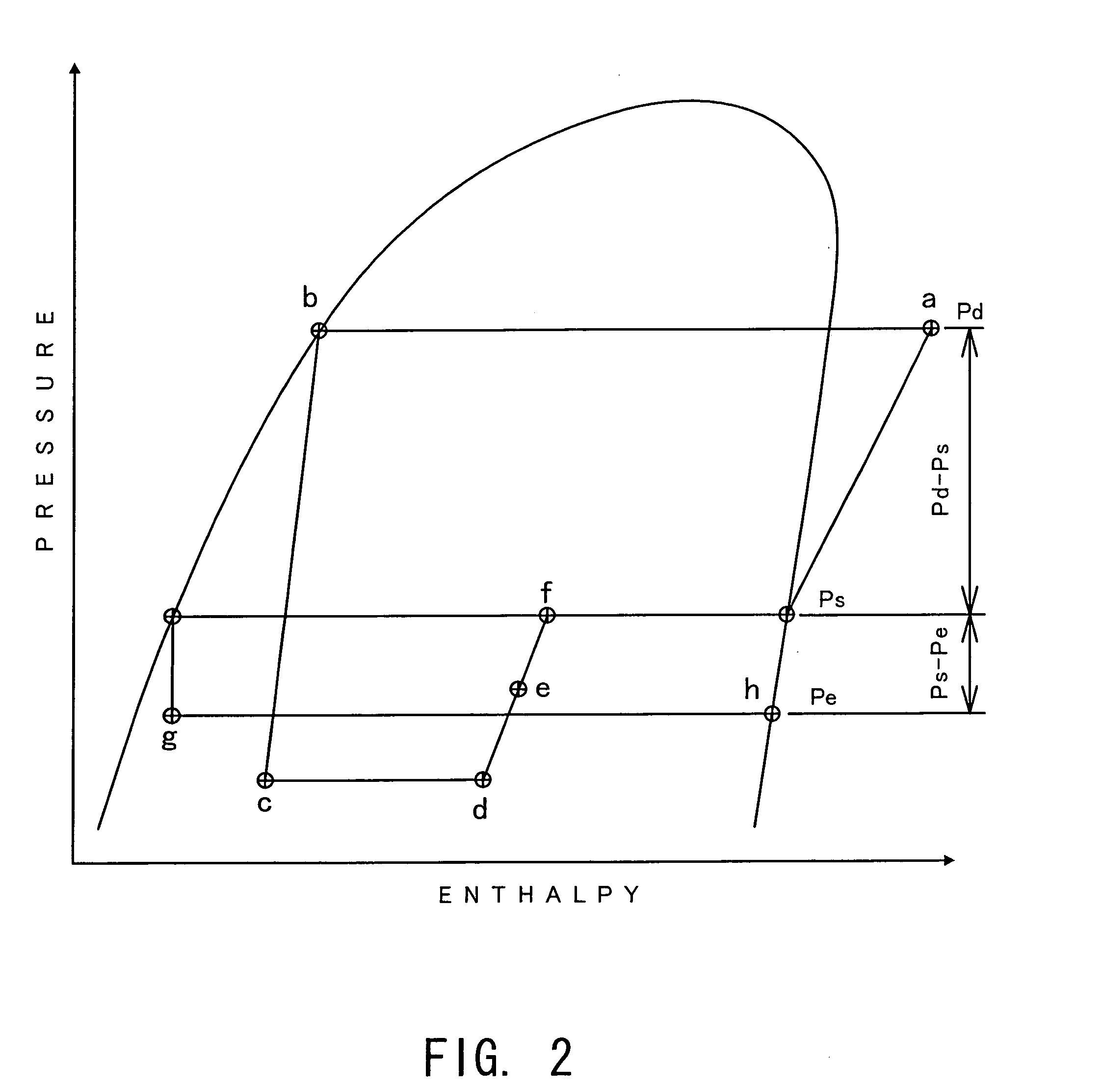
[0027]FIG. 1 is a system diagram showing a refrigeration cycle according to the present invention. FIG. 2 shows a Mollier chart which is useful in explaining the operation of the refrigeration cycle. FIG. 3 is a diagram showing characteristics of a differential pressure valve.

[0028] The refrigeration cycle according to the present invention includes a compressor 1 using an engine for driving an automotive vehicle, as a drive source. The compressor 1 is a swash plate variable displacement compressor which is capable of controlling the discharging capacity of the refrigerant to be constant, irrespective of the rotational speed of the engine. The compressor 1 incorporates an electronically controllable solenoid-driven capacity control valve 2 to thereby control the discharging capacity thereof. The capacity control valve 2 is of a so-called differential pressure control...


PUM


Abstract

The object of the present invention is to provide a refrigeration cycle for an automotive air conditioner, which is reduced in costs and uses an ejector. A variable displacement compressor driven by an engine for driving an automotive vehicle is used as a compressor, and the capacity of the compressor is controlled by a capacity control valve such that the differential pressure between discharge pressure and suction pressure of refrigerant becomes equal to a predetermined differential pressure determined by an external signal. Pressure substantially equal to pressure applied across the compressor is applied across the ejector, and therefore to control the differential pressure across the compressor is to control the differential pressure across the ejector. A differential pressure valve disposed between a gas-liquid separator and an evaporator is set to a differential pressure approximately proportional to the differential pressure across the ejector. A differential pressure set to the differential pressure valve is estimated from the differential pressure across the compressor which corresponds to the differential pressure across the ejector, and the differential pressure can be directly and accurately determined from the external signal for controlling the capacity control valve.

Description

CROSS-REFERENCES TO RELATED APPLICATIONS, IF ANY [0001] This application claims priority of Japanese Application No. 2003-276389 filed on Jul. 18, 2003 and entitled “REFRIGERATION CYCLE”. BACKGROUND OF THE INVENTION [0002] (1) Field of the Invention [0003] The present invention relates to a refrigeration cycle, and more particularly to a refrigeration cycle using an ejector in which the refrigeration cycle is applied to an automotive air conditioner. [0004] (2) Description of the Related Art [0005] Conventionally, an ejector cycle formed by using an ejector is known in the field of refrigeration cycles for use in refrigerating apparatuses, such as water heaters, refrigerator vehicles, and automotive air conditioners. The ejector cycle is constructed such that a compressor, a condenser, an ejector, and a gas-liquid separator are connected in series, and a gas outlet of the gas-liquid separator is connected to a suction port of the compressor, while a liquid outlet of the gas-liquid s...

Claims


Application Information

Patent Timeline
Patent Type & Authority Applications(United States)
IPC IPC(8): F04B27/18F04F5/04F04F5/46F04F5/48B60H1/32F25B1/00F25B27/00F25B41/00F25B41/04F25B41/06F25B43/00F25B49/02
CPCF04B27/1804F04F5/04F04F5/461F04F5/48F25B41/00F25B41/04F25B2500/19F25B49/022F25B2309/06F25B2341/0012F25B2400/0407F25B2400/0409F25B2500/18F25B43/006B60H2001/3298
Inventor HIROTA, HISATOSHI
Owner TGK
Why Eureka
Try Eureka