Refrigerant hose

a technology for refrigerant hoses and hoses, which is applied in the direction of synthetic resin layered products, friction elements, other domestic articles, etc., can solve the problem that rubber materials generally tend to have high gas permeability, and achieve the effect of low permeation

Inactive Publication Date: 2005-01-20
VEYANCE TECH
View PDF16 Cites 9 Cited by
  • Summary
  • Abstract
  • Description
  • Claims
  • Application Information

AI Technical Summary

Benefits of technology

[0005] The present invention is directed to a hose comprising a core layer, an elastomeric friction layer overlaying the core layer, at least one reinforcement layer overlaying the friction layer, a

Problems solved by technology

However, rubber materials generally

Method used


Image

  • Refrigerant hose
  • Refrigerant hose

Examples


example

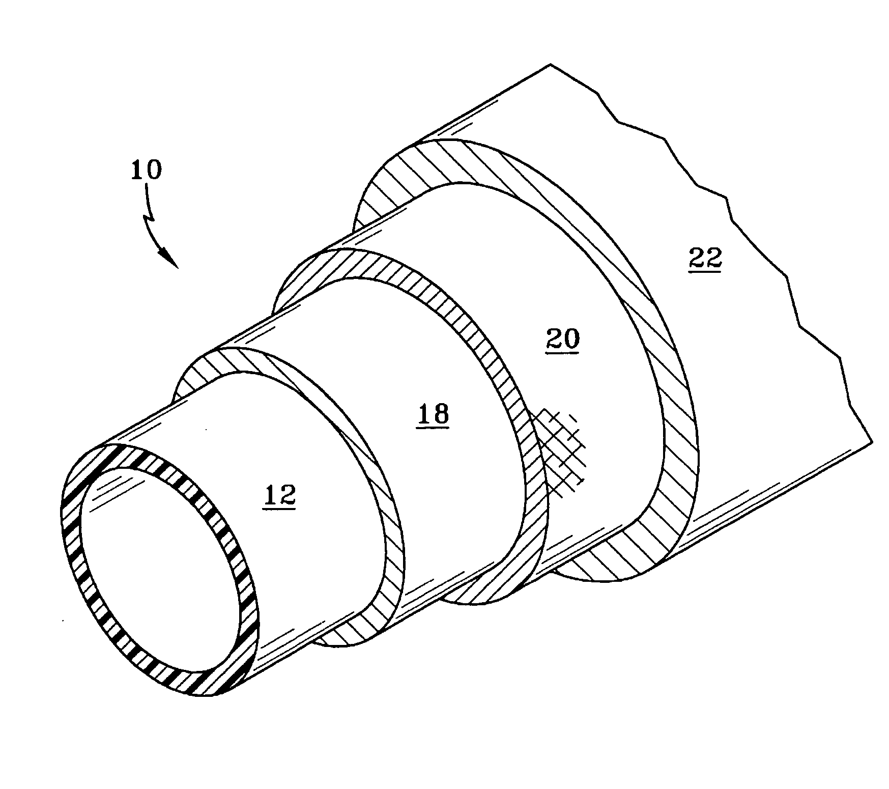
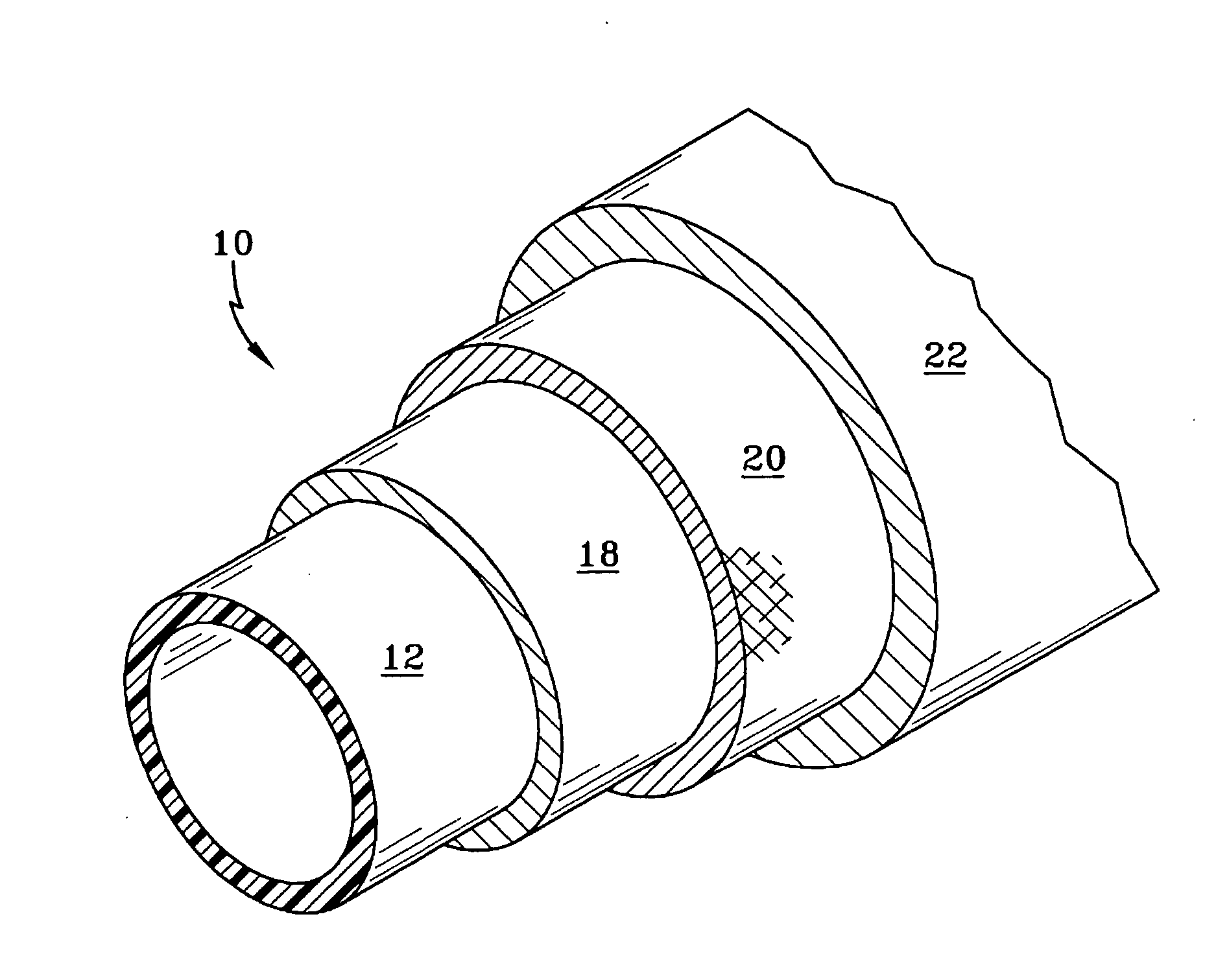
[0016] A hose 10 was built in accordance with the present invention, having a core with a polyamide blend, an EPDM friction layer, an aramid reinforcement, and an AEM cover. The core 12 was formed by extruding a 2 to 1 weight ratio of nylon 6 and nylon 6, 66. The core 12 had a gauge of about 0.3-0.4 mm.

TABLE 1polyamide 11polyamide 22blendTensile Strength, MPa 38 7028% Elongation at Break337368243Permeation Rate*, g / m / day——0.23

*measured with R134A refrigerant, 10 days at 90° C.

1FN727, a nylon 6, obtained from DuPont

2non-plasticized copolymer of nylon 6 and nylon 66 obtained from Atofina

[0017] The hose was tested for 10 days at 90° C. following Volkswagen Specification TL 823 16 to determine the permeation rate. The permeation rate was 0.23 μm / day, and the exemplary hose is a low permeation hose.


PUM

PropertyMeasurementUnit
Dynamic viscosityaaaaaaaaaa
Weight ratioaaaaaaaaaa

Abstract

A hose comprising a core layer, an elastomeric friction layer overlaying the core layer, at least one reinforcement layer overlaying the friction layer, and a cover layer overlaying the at least one reinforcement layer, wherein the core layer is comprised of a blend of two different non-plasticized polyamides.

Description

CROSS-REFERENCE TO RELATED APPLICATION [0001] This application claims the benefit of co-pending Ser. No. 60 / 486,520, fully incorporated herein by reference.FIELD OF THE INVENTION [0002] The disclosed invention relates to refrigerant hoses for use in automotive and industrial air conditioners. BACKGROUND OF THE INVENTION [0003] The automotive industry uses hoses for transporting refrigerants. The hoses generally have a three-layer laminar construction consisting of an innermost layer, an outermost cover layer located radially outwardly of the inner tube, and a reinforcing fiber layer interposed between the innermost layer and the outermost layer. Generally, the inner and outer layers are formed of rubber. The reinforcing fiber layer usually is a mesh structure formed by braided organic yarn such as polyester fiber, rayon fiber, or nylon fiber. The outer cover typically is formed of ethylene propylene diene rubber (EPDM) or chloroprene rubber (CR). Adhesion layers be may employed betw...

Claims


Application Information

Patent Timeline
IPC IPC(8): B32B1/08F16L11/08B32B25/08B32B27/34F16L11/02F16L11/04F16L11/06F16L11/10F16L11/12
CPCB32B1/08B32B27/34B60H1/00571Y10T428/1393F16L11/08F16L11/12F16L11/06F16L11/081F16L11/085F16L2011/047F16L11/04F16L11/02F16L11/10B32B2475/00B32B25/08B32B2270/00B32B2597/00B32B2323/16
Inventor WILSON, REJI PAULNADKARNI, PRADEEP DATTATRAYAKOZAK, ROBERT JOHN
Owner VEYANCE TECH
Why Eureka
Try Eureka