Lubrication device for stagegeared gearbox

Inactive Publication Date: 2005-01-20
VOLVO LASTVAGNAR AB
View PDF13 Cites 0 Cited by
  • Summary
  • Abstract
  • Description
  • Claims
  • Application Information

AI Technical Summary

Benefits of technology

[0018] The advantage to this arrangement is that the first duct, which is the inlet duct to the pump, can be located as far away as p

Problems solved by technology

Furthermore, if a range transmission is arranged at the back of the gearbo

Method used


Image

  • Lubrication device for stagegeared gearbox
  • Lubrication device for stagegeared gearbox
  • Lubrication device for stagegeared gearbox

Examples


Embodiment Construction

[0037] A lubrication device configured according to the present invention is described hereinbelow in greater detail with reference to FIGS. 7 through 11.

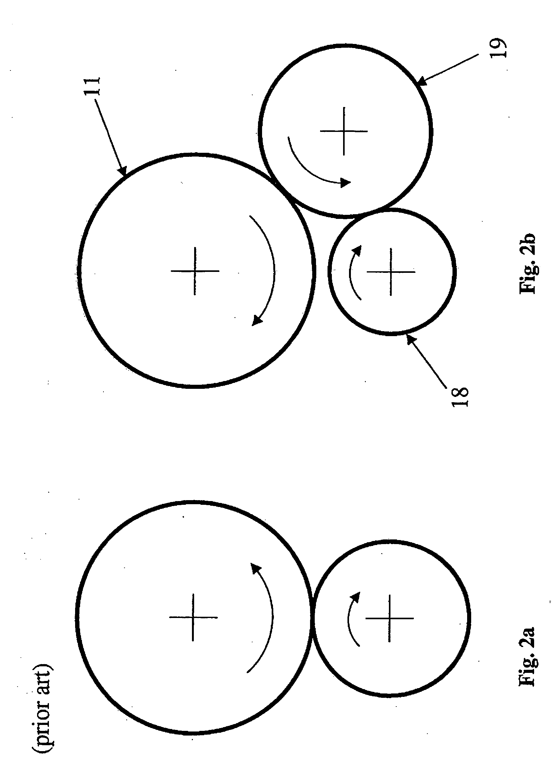
[0038] The aforementioned disadvantages to existing locations of an oil pump 24 may be overcome by relocating the oil pump directly in front of a reverse intermediate gear 19; that is to say, between the reverse intermediate gear 19 and a reverse gear shaft lug 22. This is shown in FIG. 7. According to the exemplary embodiment shown in FIG. 7, the oil pump 24 is of an internal geared type. This type of oil pump is shown in more detail in FIG. 8. The rotating parts of such a pump comprise two pieces; an inner rotor 32 and an outer rotor 33 eccentrically mounted in relation thereto. The inner rotor 32 has external teeth, which mesh with internal teeth on the outer rotor 33. The inner rotor 32 has a hole in its center through which a shaft runs. According to the invention the shaft is represented by the reverse gear shaft 20 (see FIG...


PUM


Abstract

Method and arrangement for providing a lubrication device for a stage-geared gearbox (1, 2) arranged in a motor vehicle. The gearbox (1, 2) has an input shaft (4), intermediate shaft (5), which has at least one gear meshing with a gear on the input shaft (4). A main shaft (6) is provided with gears (7, 8, 9, 10) which mesh with gears on the intermediate shaft. One gear (11, 18) on both the intermediate shaft (5) and the main shaft (6) are for reverse. A reverse gear shaft (20) is supported in the casing (16, 21) and in a reverse gear shaft lug (22), the reverse gear shaft lug in turn being fixed in the casing (16). A reverse intermediate gear (19) is arranged on the reverse gear shaft (20) between the reverse gear shaft lug (22) and the bearing point for the reverse gear shaft in the casing (21). The reverse intermediate gear (19) meshes with the two corresponding gears (11, 18) for reverse gears. The lubrication device includes a lubricant pump (24) that is arranged between bearing points (16, 21, 22) of the reverse gear shaft (20). An oil filter (28) is arranged in the cover (54).

Description

CROSS-REFERENCE TO RELATED APPLICATIONS [0001] The present application is a continuation patent application of International Application No. PCT / SE03 / 00196 filed 5 Feb. 2003 which was published in English pursuant to Article 21(2) of the Patent Cooperation Treaty, and which claims priority to Swedish Application No. 0200440-6 filed 14 Feb. 20025. Said applications are expressly incorporated herein by reference in their entireties.TECHNICAL FIELD [0002] The present invention relates to a device for delivering lubricating oil in a gearbox, which is arranged in a motor vehicle. BACKGROUND ART [0003]FIG. 1 shows a longitudinal section through a known configuration for a manually shifted gearbox 1 for a truck. The front parts of the gearbox are shown to the left in FIG. 1, which is to say, towards the vehicle engine. The rear parts of the gearbox are shown to the right in FIG. 1. The gearbox comprises (includes, but is not necessarily limited to) a basic gearbox 2, having a plurality of ...

Claims


Application Information

Patent Timeline
IPC IPC(8): F16H57/04
CPCF16H57/0404F16H57/0494F16H57/045F16H57/0441
Inventor HEDMAN
Owner VOLVO LASTVAGNAR AB
Why Eureka
Try Eureka