BAW resonator

a resonator and waveform technology, applied in the direction of impedence networks, electric devices, etc., can solve the problems of unbalanced/balanced signals that cannot be balanced/unbalanced, piezolayers whose thicknesses are extremely thin, and cannot be balanced/unbalanced, so as to increase the scope of possible applications and increase the available frequency range.

Inactive Publication Date: 2005-01-20
AVAGO TECH INT SALES PTE LTD
View PDF9 Cites 47 Cited by
  • Summary
  • Abstract
  • Description
  • Claims
  • Application Information

AI Technical Summary

Benefits of technology

The present invention is based on the findings that the disadvantages, discussed at the outset, of prior art BAW filters and / or prior art BAW resonators may be avoided in that the BAW resonators comprise piezoelectric layers and / or portions in a piezoelectric material, whose orientations are opposed to one another (are aligned in an inverted manner). In this way, firstly, it is possible to significantly increase the scope of possible applications of such BAW resonators, and, secondly, it is possible to increase the available frequency ranges for the use of such BAW resonators.

Problems solved by technology

The disadvantage of these prior art BAW filters is that no filter topology is known which converts signals from unbalanced / balanced signals to balanced / unbalanced signals without entailing restrictions with regard to the common-mode load impedance toward mass, or which can do without the additional coils or transformers / converters.
A further disadvantage of these prior art BAW filters is that they include, at frequencies of more than 5 GHz, piezolayers whose thicknesses for a fundamental-mode wave (fundamental-mode BAW) are extremely thin (<300 nm).
A further disadvantage is that at such frequencies of more than 5 GHz, those resonators which have a predetermined impedance level are smaller than is desired for performance reasons, since this yields, for example, a poor ratio of area and circumference of the arrangement, which leads to strong parasitic effects.
Yet another disadvantage of the prior art BAW filter is the fact that the thickness of a piezolayer for a fundamental-mode wave (fundamental-mode BAW) will be quite thick (>5 μm) at frequencies below 500 MHz.
This leads to the added disadvantage that considering a dielectric constant of 10 (of the substrate), a respective individual resonator having an impedance level of 50 ohm will require an area of >0.5 mm2.
Even though in the prior art solutions have been known by means of which the problem of converting balanced / unbalanced signals into unbalanced / balanced signals is made possible, these solutions, too, pose the above-mentioned problems in connection with the common-mode load impedance toward mass, and / or in connection with the use of additional devices.
The prior art has known solutions for filter arrangements for frequencies above 5 GHz, but it is cavity resonators or ceramic resonators that are typically used for this purpose, which are both rather bulky, lossy in terms of electricity and very expensive.
Filter operations in the range from 100 MHz to 2 GHz are performed mainly using surface acoustic wave filters (SAW Filters), which have the drawback that they are rather bulky and are, in addition, very expensive in the range of less than 500 MHz.

Method used


Image

  • BAW resonator
  • BAW resonator
  • BAW resonator

Examples


first embodiment

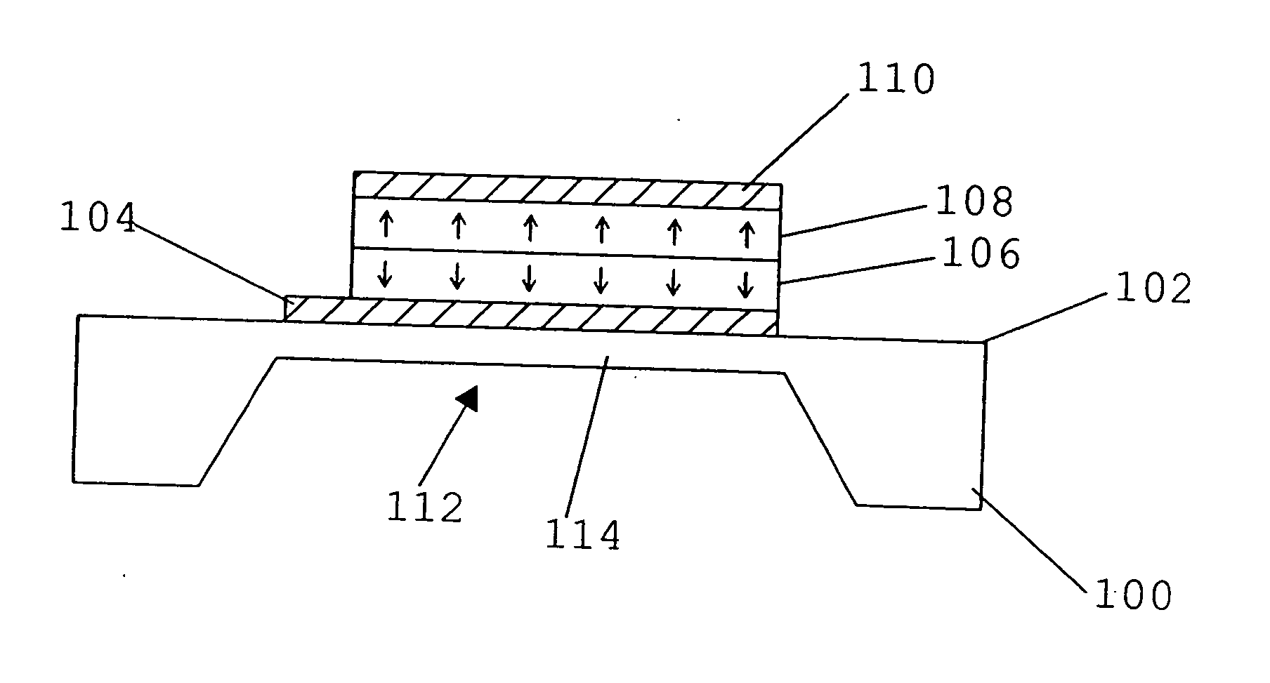
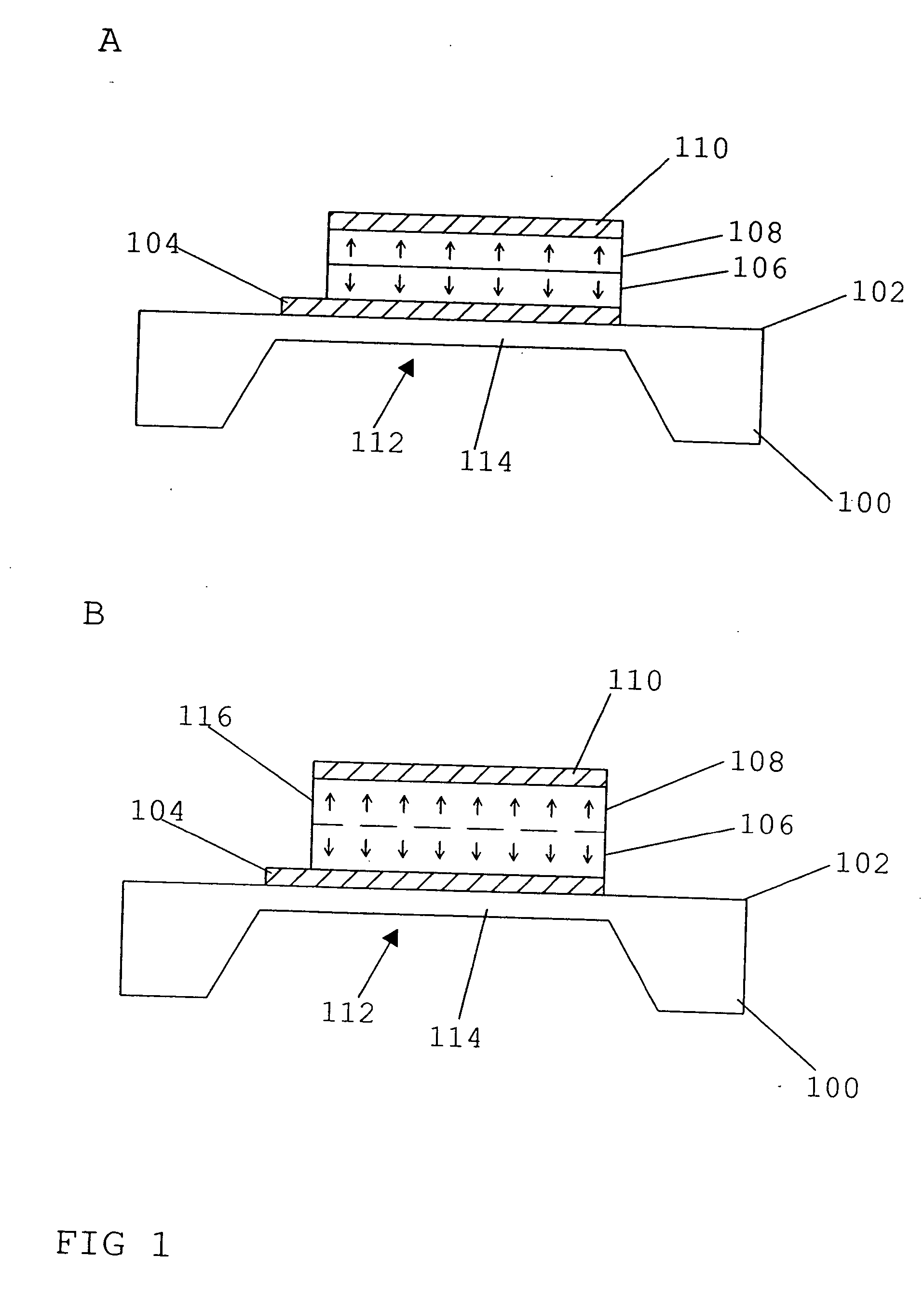
FIG. 1A shows a BAW resonator in accordance with the present invention. The BAW resonator includes a substrate 100 comprising a first main surface 102 which has a first lead electrode 104 made of a metal or another conductive material formed thereon. Electrode 104 has a first piezoelectric layer 106 arranged thereon, which, in turn, has a second piezoelectric layer 108 arranged thereon. A second electrode 110 made of a metal or another conductive material is arranged on the piezoelectric layer 108. The first electrode 104 is, for example, an input electrode, and the second electrode 110 is, for example, an output electrode. Substrate 100 includes a recess 112 for forming a diaphragm area 114 which has the BAW resonator formed thereon so as to label acoustic decoupling of the resonator from underlying elements and / or layers. Alternatively, decoupling may also be achieved by a so-called acoustic reflector which would then be arranged between substrate 100 and electrode 104. Both decou...

second embodiment

FIG. 1B represents the inventive BAW resonator, which embodiment differs from the embodiment described with reference to FIG. 1A in that a piezoelectric material 116 is arranged between electrodes 104 and 110 instead of the two separated piezoelectric layers 106 and 108. Thus, only one piezoelectric layer 116 is provided. However, layer 116 is made such that it comprises a first portion 106 and a second portion 108, in which the alignments or orientations (polarization) of the material of the piezoelectric layer 116 are mutually opposed, as is shown by the arrows. The various portions are separated by the dashed line in FIG. 1B.

The layer 116 shown in FIG. 1B is made, for example, such that the first portion 106 is initially grown using process parameters enabling the alignment shown there. Subsequently, the second portion 108 is grown to the thus produced portion 106, using other process parameters so as to achieve the opposed orientation in portion 108, FIG. 1B. In this case, the ...


PUM

PropertyMeasurementUnit
frequenciesaaaaaaaaaa
areaaaaaaaaaaa
impedanceaaaaaaaaaa

Abstract

A BAW resonator includes a first piezoelectric layer made of a material oriented toward a first direction, and a second piezoelectric layer made of a material oriented toward a second direction which is opposed to the first direction. The first piezoelectric layer and the second piezoelectric layer are acoustically coupled with each other.

Description

BACKGROUND OF THE INVENTION 1. Field of the Invention The present invention relates to a BAW resonator (BAW=bulk acoustic wave). In particular, the present invention relates to BAW resonators having a plurality of layers comprising different material orientations. In addition, the present invention relates to BAW filters comprising such BAW resonators. 2. Description of Prior Art BAW filters comprising one or several BAW resonators, e.g. in a ladder-type circuit, have been known in the art. The BAW resonators used for these BAW filters are so-called thin-film BAW resonators, i.e. resonators comprising a piezoelectric thin film. The disadvantage of these prior art BAW filters is that no filter topology is known which converts signals from unbalanced / balanced signals to balanced / unbalanced signals without entailing restrictions with regard to the common-mode load impedance toward mass, or which can do without the additional coils or transformers / converters. A further disadvantage...

Claims


Application Information

Patent Timeline
Patent Type & Authority Applications(United States)
IPC IPC(8): H03H9/00H03H9/17H03H9/58
CPCH03H9/0095H03H9/174H03H9/175Y10T29/42H03H9/178H03H9/581H03H9/583H03H9/176H03H9/02015
Inventor AIGNER, ROBERTHANDTMANN, MARTINMARKSTEINER, STEPHANNESSLER, WINFRIED
Owner AVAGO TECH INT SALES PTE LTD
Why Eureka
Try Eureka