Micro-electro-mechanical switch, and methods of making and using it

a micro-electro-mechanical switch and switch technology, applied in the field of switches, can solve the problems of not being able to carry the switch is no longer capable of carrying out the switching function, and the electric charge from the membrane can tunnel into and become trapped in the dielectric layer, etc., to achieve the effect of increasing the operational li

Inactive Publication Date: 2005-01-20
RAYTHEON CO
View PDF16 Cites 166 Cited by
  • Summary
  • Abstract
  • Description
  • Claims
  • Application Information

AI Technical Summary

Benefits of technology

[0013] From the foregoing, it may be appreciated that a need has arisen for a method and apparatus for making and operating a switch of the type having a flexible membrane, in a manner so that the switch has a significantly increased operational lifetime. According to the present invention, a method and apparatus are provided to address this need.
[0014] More specifically, according to one form of the invention, a switch includes a base having a first section which includes an electrically conductive part, and also includes a membrane having first and second ends supported at spaced locations on the base, and having between the ends a second section which includes an electrically conductive portion. The membrane is capable of resiliently flexing so as to move between first and second positions, the conductive part and the conductive portion being physically closer in the second position than in the first position. One of the first and second sections has a textured surface, and the other thereof has a further surface which faces the textured surface, the textured surface having mutually exclusive first and second portions which are respectively in physical contact with and free of physical contact with the further surface when the membrane is in the second position. The first portion of the textured surface has an area which is substantially less than a total area of the textured surface.
[0015] According to a different form of the invention, a switching method uses a switch that includes a base having a first section with an electrically conductive part, and that includes a membrane having first and second ends supported at spaced locations on the base, and having between the ends a second section which includes an electrically conductive portion, where one of the first and second sections has a textured surface and the other

Problems solved by technology

Although existing switches of this type have been generally adequate for their intended purposes, they have not been satisfactory in all respects.
One problem is that, when the membrane is contacting the dielectric layer in the actuated state of the switch, electric charge from the membrane can tunnel into and become trapped in the dielectric layer.
As a result, the membrane becomes trapped in its actuated position, and the switch is no longer capable of carrying out a switching function.
This is considered a failure of the switch, and is associated with an undesirably short operational lifetime for the switch.
In this regard, an RF MEMS switch of this type should be capable of trillions of switching cycles before a failure occurs due to fatigue in the

Method used


Image

  • Micro-electro-mechanical switch, and methods of making and using it
  • Micro-electro-mechanical switch, and methods of making and using it
  • Micro-electro-mechanical switch, and methods of making and using it

Examples


Embodiment Construction

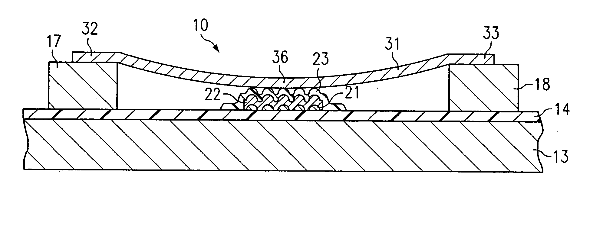
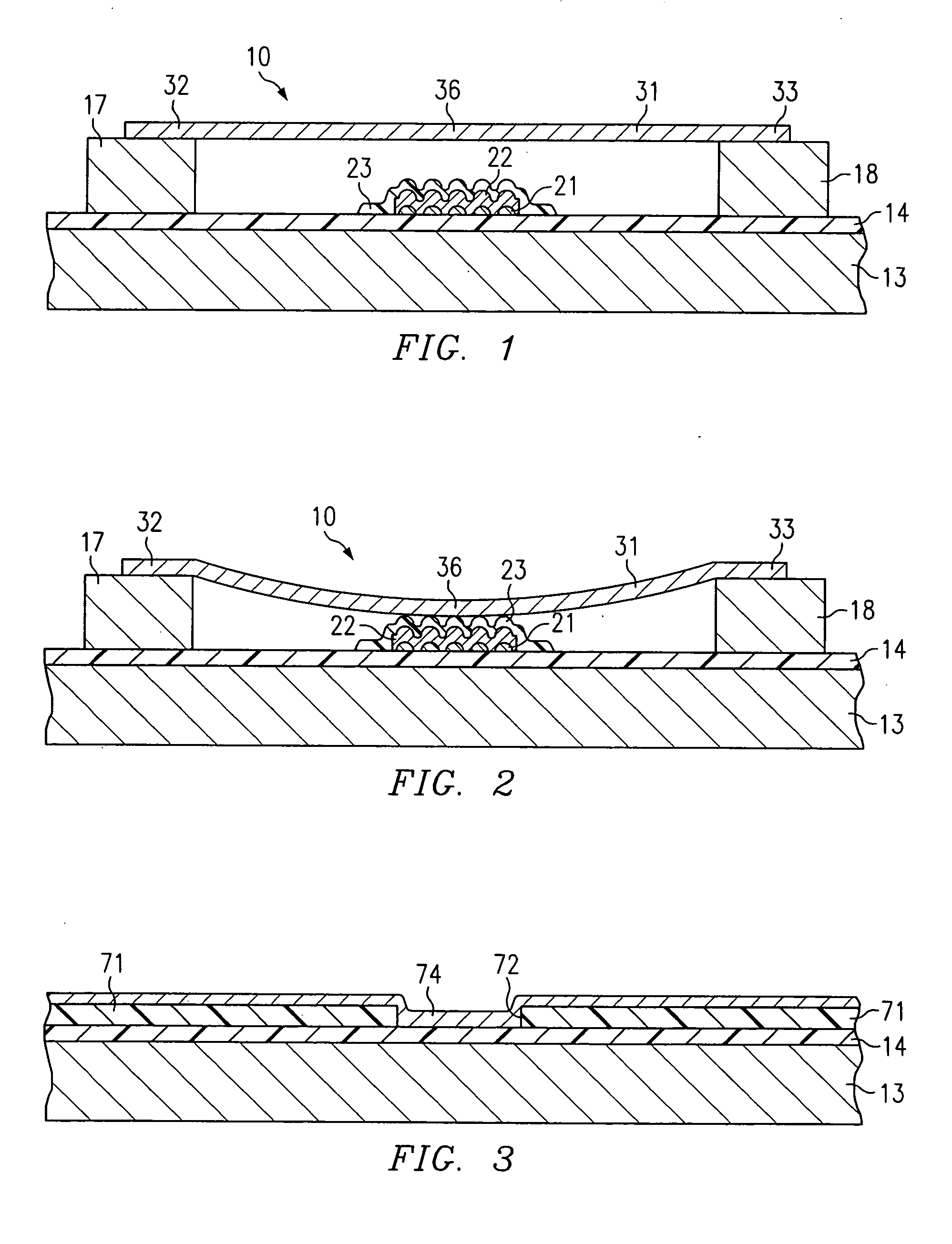
[0027]FIG. 1 is a diagrammatic fragmentary sectional side view of an apparatus which includes a micro-electro-mechanical switch (MEMS) 10, the switch 10 embodying aspects of the present invention. The drawings, including FIG. 1, are diagrammatic and not to scale, in order to present the switch 10 in a manner which facilitates a clear understanding of the present invention.

[0028] With reference to FIG. 1, the switch 10 includes a silicon semiconductor substrate 13 having on an upper side thereof an oxide layer 14. Although the substrate 13 is a made of silicon in this disclosed embodiment, it could alternatively be made of some other suitable material, such as gallium arsenide (GaAs), or a suitable alumina. Similarly, the oxide layer 14 is silicon dioxide in this disclosed embodiment, but could alternatively be some other suitable material.

[0029] Two posts 17 and 18 are provided at spaced locations on the oxide layer 14, and are each made of a conductive material. In this embodimen...


PUM


Abstract

A micro-electro-mechanical (MEMS) switch (10, 110) has an electrode (22, 122) covered by a dielectric layer (23, 123), and has a flexible conductive membrane (31, 131) which moves between positions spaced from and engaging the dielectric layer. At least one of the membrane and dielectric layer has a textured surface (138) that engages the other thereof in the actuated position. The textured surface reduces the area of physical contact through which electric charge from the membrane can tunnel into and become trapped within the dielectric layer. This reduces the amount of trapped charge that could act to latch the membrane in its actuated position, which in turn effects a significant increase in the operational lifetime of the switch.

Description

RELATED APPLICATIONS [0001] The present application is a divisional of U.S. Ser. No. 10 / 140,658 filed May 7, 2002, entitled Micro-Electro-Mechanical Switch, and Methods of Making and Using It, now U.S. Pat. No. ______.TECHNICAL FIELD OF THE INVENTION [0002] This invention relates in general to switches and, more particularly, to micro-electro-mechanical switches having flexible membranes. BACKGROUND OF THE INVENTION [0003] One existing type of switch is a radio frequency (RF) micro-electro-mechanical switch (MEMS). This existing type of switch has a substrate with two spaced and conductive posts thereon. A conductive part is provided on the substrate between the posts, and is covered by a layer of a dielectric material. A flexible and electrically conductive membrane extends between the posts, so that a central portion of the membrane is located above the conductive part on the substrate. An RF signal is applied to one of the conductive part and the membrane. [0004] In the deactuate...

Claims


Application Information

Patent Timeline
IPC IPC(8): H01H1/06H01H59/00
CPCB81B3/0008B81B2201/014B81B2203/0118H01H2059/0072H01H59/0009H01H2059/0018H01H1/06B81B3/001B81B2203/04
Inventor PILLANS, BRANDON W.FOREHAND, DAVID I.
Owner RAYTHEON CO
Why Eureka
Try Eureka