Write head layout

a writing head and pattern layout technology, applied in the field of magnetic recording heads, can solve the problems of reducing the usable area of the media and thus the usable capacity of the recording media, affecting the readout of data, and affecting the usability of the recording media

Inactive Publication Date: 2005-01-20
O MASS
View PDF12 Cites 16 Cited by
  • Summary
  • Abstract
  • Description
  • Claims
  • Application Information

AI Technical Summary

Benefits of technology

[0016] to provide a write head configuration that will, due to the position of pole pieces with respect to other parts of this head, allow the placement of two write heads adjacent to or very close (a distance of one track width) to each other without any offset in the direction of media movement;
[0017] allow for adjacent rows (or columns) in the matrix head with a significantly reduced requirement for azimuth alignment;
[0018] eliminate the guard band between adjacent rows (or columns) in the matrix head;
[0023] provide a write gap matrix layout that will ensure the track width to be defined by being overwritten by an adjacent track and eliminating the occurrence of a guardband between two adjacent tracks.

Problems solved by technology

This layout will work well for one row (or column) of data, but a problem will occur when a new row (or column) is to be added to create additional adjacent tracks.
P00,1952, entitled “Fully Integrated Matrix Magnetic Recording Head With Independent Control” but such a solution reduces the usable area of the media and thus also usable capacity of the recording media.
The second disadvantage is that the total width of the pack of tracks written by such a pattern layout of the matrix array of heads will significantly vary in width due to any angular misalignment between the matrix array of the heads and the recording media.
As the read head will have in some way to match and read the written tracks, the above mentioned effects of varying the track pitch, the track width and the track pack width, makes the readout of the data complicated.
Another problem occurs as the track width becomes smaller.
Tolerances related to position of the gap ends will thus cause either overwrite or a guardband between two adjacent tracks.
Another problem is related to the readout of the outermost tracks.
Nevertheless these patent documents applications do not provide a solution to the above-mentioned problems.

Method used


Image

  • Write head layout
  • Write head layout
  • Write head layout

Examples


Embodiment Construction

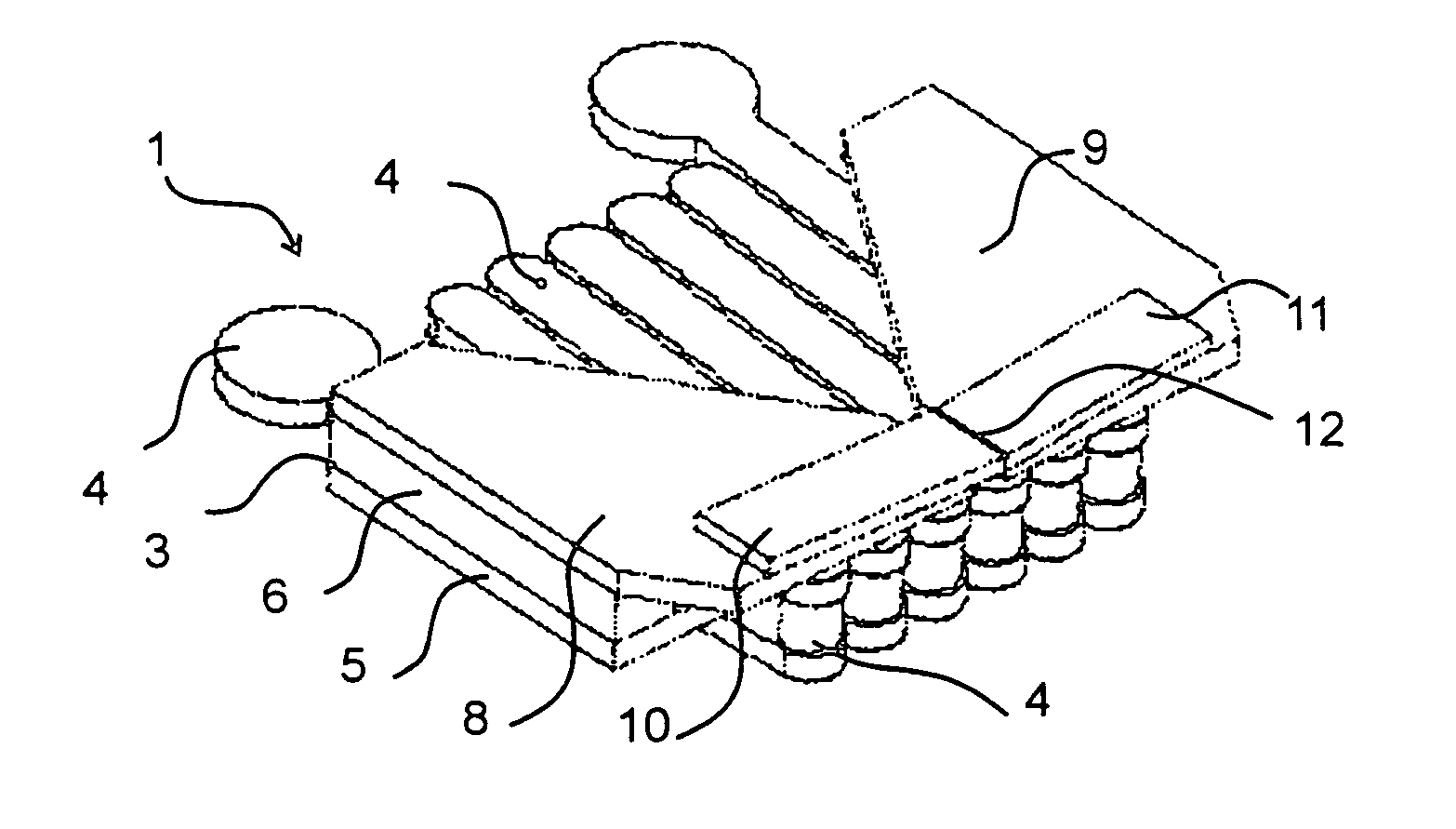
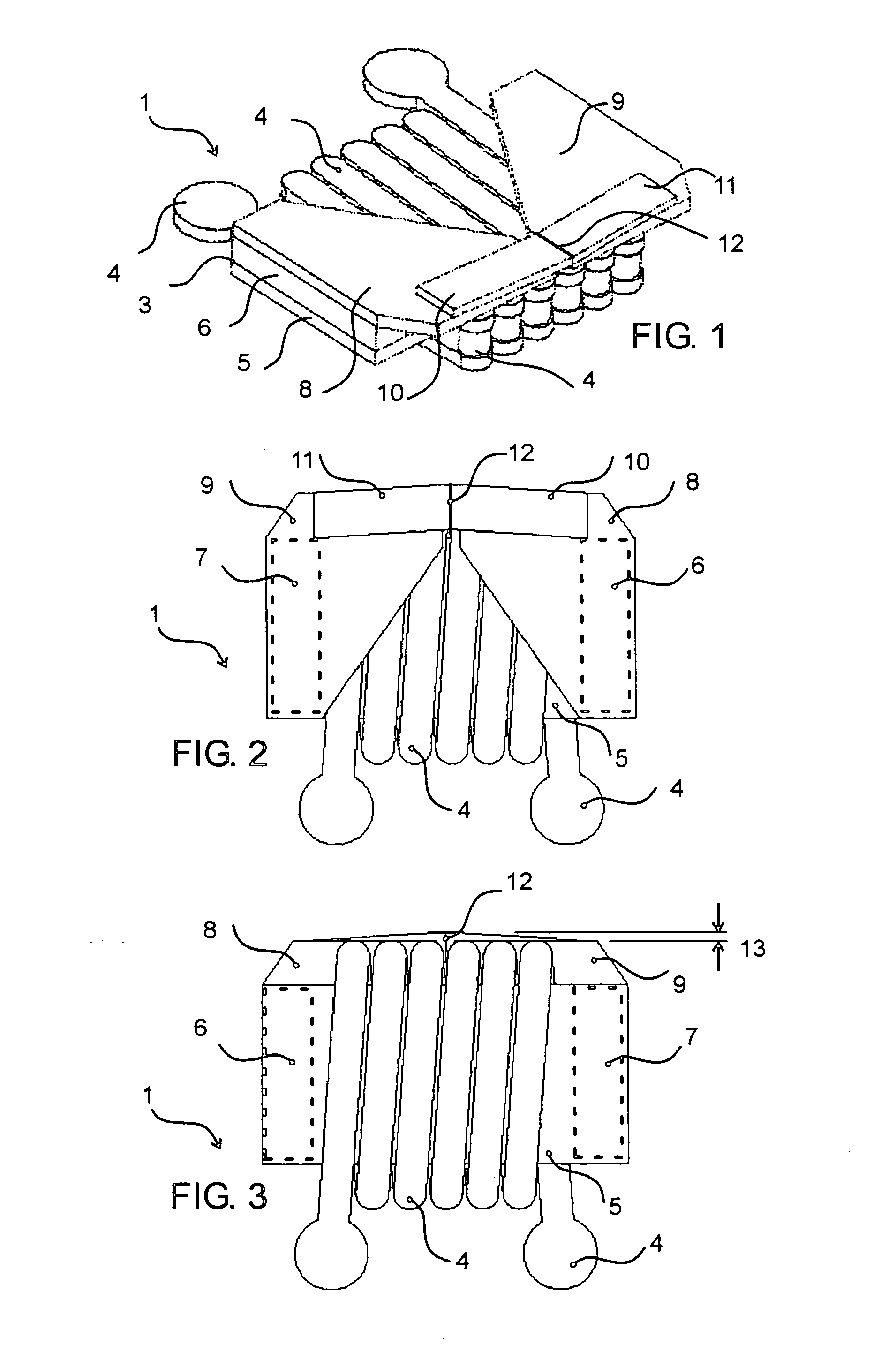
[0045]FIG. 1 shows an individual write head corresponding to one cell of the matrix array. The illustrated write head, which is formed of thin films, is shown disembodied from the matrix structure of which it forms a part during use of the write head. The write head is formed by a magnetic circuit 3 and an excitation conductor 4 , all being fabricated on a non-magnetic substrate or wafer 1. The magnetic circuit 3 is formed of a bottom pole piece 5, two pillars 6 and 7 (FIG. 2) and two concentrators 8 and 9. Directly on the concentrators are two poles 10 and 11 that form a writing gap 12. The substrate 1, also referred to as a chip or wafer, is indicated generally in the figure as 1, and is understood to be the planar member on which or in which the write head is formed.

[0046]FIG. 2 shows a top view of the write head, including an outline view of the pillars 6 and 7 beneath and at the sides of the concentrators 8 and 9. The concentrators 8 and 9 overlie the excitation conductors 4. ...


PUM

PropertyMeasurementUnit
widthaaaaaaaaaa
movementaaaaaaaaaa
gap widthaaaaaaaaaa

Abstract

A matrix write head for recording data on recordable magnetic media includes an arrangement of write heads on a substrate. The write heads have write gaps which are arranged in a plough configuration. A very small guard band, or none at all, is provided between the tracks written by the write heads. Read gaps may be provided on the substrate, as well as edge detectors.

Description

BACKGROUND OF THE INVENTION [0001] 1. Field of the Invention [0002] The present invention relates generally to a magnetic recording head and, more particularly, to a matrix-type thin film magnetic recording head for recording of multiple tracks on recording tapes, for example. [0003] 2. Discussion of the Related Art [0004] In order to satisfy the increasing performance requirements of magnetic storage devices (for example, hard-discs, tape drives, or floppies—also termed floppy discs), ever increasing area densities and data rates are required. The area density is limited by lateral tape motions, residual head servo tracking errors, mechanical tolerances on the head, thermal and hygroscopic coefficient of expansion of the media, etc. [0005] Writing and reading simultaneously of several tracks in parallel seems to be an increasingly widely used approach how to achieve both high area densities and high data rates. On standard multiple heads, the minimum distance which is necessary bet...

Claims


Application Information

Patent Timeline
Patent Type & Authority Applications(United States)
IPC IPC(8): G11B5/127G11B5/187G11B5/31G11B5/48G11B5/49
CPCG11B5/127G11B5/187G11B5/4976G11B5/4893G11B5/3183
Inventor RUBAS, LADISLAVRUDI, GUTTORMNYMOEN, ARNERAASTAD, JORN
Owner O MASS
Why Eureka
Try Eureka