Technique of determining connectivity solutions for network elements

a technology of network elements and connectivity solutions, applied in data switching networks, frequency-division multiplexes, instruments, etc., can solve the problems of inefficient process, time-consuming iterations between nms and each of the ems, and multiple exchange of protocols, so as to achieve the effect of effective performing the process

Active Publication Date: 2005-01-20
ECE TELECOM LTD
View PDF9 Cites 49 Cited by
  • Summary
  • Abstract
  • Description
  • Claims
  • Application Information

AI Technical Summary

Benefits of technology

It is therefore an object of the present invention to provide such a technology for finding connectivity solutions in a network comprising a great number of switching network elements and NMS, which enables effectively performing it at the NMS level.
It should be emphasized that, in the preferred version of the present invention, the NMS does not have to know (store) the connectivity structure of each and every network element (NE). Instead, it stores a single and relatively small connectivity table (CT) which is built to reflect common connectivity rules in the network elements and thus effectively assists in finding real connectivity solutions. Some additional information might be held in the NMS, which will be mentioned later on.
The search for a connectivity solution (either using the CT composed from the component connectivity tables, or using the CT of common connectivity rules) may be terminated by checking information on busy connections. In particular, it can be made by preliminary providing and further referring to a data base of busy connections (or a so-called hash table HT) in the NMS, indicating internal connections which are presently occupied in the network elements. The HT is composed of a plurality of Hash sub-tables assigned to respective network elements. Each of the Hash sub-tables comprises only a list of busy internal connections of the element, and therefore is economical from the point of memory since there is no need in storing status of all possible real connections which might be arranged in the NE between all its input and output connection points.

Problems solved by technology

The switching elements not only comprise various types of ports and connections, but usually have particular equipment limitations so that not each and every input connector can work with an arbitrary output connector of the same or other switching element in the network.
There may be a number of reasons for such limitations, including differences in protocols, physical characteristics, incompatible locations in space, preferred or non-preferred connections, cost-related limitations etc.
The iterations between the NMS and each of the EMS are time consuming, require multiple exchange of protocols.
As a result, the process requires more time and is inefficient.

Method used


Image

  • Technique of determining connectivity solutions for network elements
  • Technique of determining connectivity solutions for network elements
  • Technique of determining connectivity solutions for network elements

Examples


Embodiment Construction

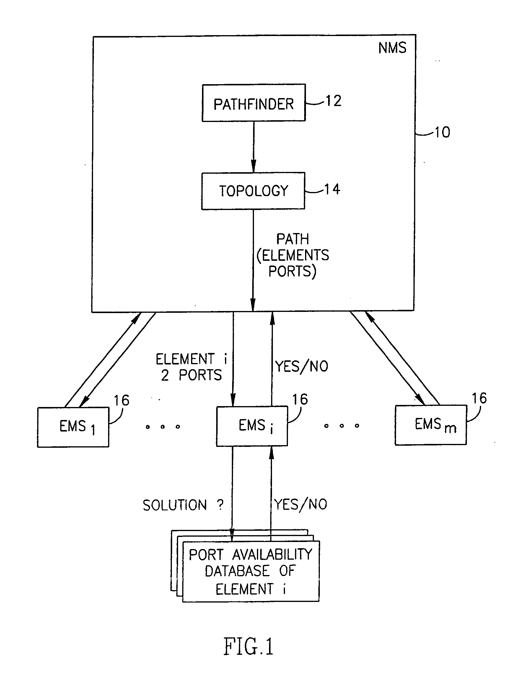
FIG. 1 illustrates a known type of interaction between NMS and EMS for finding a connectivity solution in a network element selected to form part of a path in a network (not shown). NMS (Network Management System) is marked 10 and comprises a pathfinder program (marked 12) and data on the network topology (marked 14), which is usually built as a graph reflecting the existing network elements, ports and arrangement of the elements in the network. The pathfinder's function is to select a path in the network according to a number of conditions and based on the network topology, and to form in the NMS a request indicating particular network elements and ports thereof which are to be utilized (i.e., the selected input port and the selected output port). The information on the selected ports are then transmitted from the NMS to EMS (Element Management System) of each element selected for the path (the EMS blocks: 1, i . . . n are marked with 16). The EMS of a particular network element lo...


PUM


Abstract

A technique of finding connectivity solutions for network elements to be switched into a path selected in a network managed by a network management system (NMS), wherein each network element comprises input ports and output ports, each of the ports enabling a plurality of connection points, the technique including providing, at the level of NMS, a connectivity table (CT) comprising data on possible internal connections between connection points of any input port and any output port of any of the network elements managed by the NMS. The technique enables, whenever a particular network element is selected with its input port and its output port to be used in the path, obtaining a connectivity solution for the particular network element at the level of NMS.

Description

FIELD OF THE INVENTION The invention relates to allocating connectivity solutions for network elements, using functionality of a Network Manager System controlling the elements in a telecommunication network. BACKGROUND OF THE INVENTION Modern telecommunication networks comprise huge numbers of network nodes (network elements), and a great number of the nodes are switching elements such as cross-connects having a complex system of input and output ports. Each of the input and output ports usually comprises a plurality of connections and is characterized by various functions. For example, some output ports may serve for dropping portions of a signal, while other output ports provide a throughput of the inputted signal. The switching elements not only comprise various types of ports and connections, but usually have particular equipment limitations so that not each and every input connector can work with an arbitrary output connector of the same or other switching element in the net...

Claims


Application Information

Patent Timeline
Patent Type & Authority Applications(United States)
IPC IPC(8): H04L45/42
CPCH04L41/0806H04L41/0856H04L45/42H04L41/12H04L41/0866
Inventor PAPOUSHADO, ISRAELSHEMESH, AVRAHAMYAM, ANAT
Owner ECE TELECOM LTD
Why Eureka
Try Eureka