Higher order mode dispersion compensating fiber and mode converter for higher order fiber

a higher-order fiber and mode converter technology, applied in the direction of optical fibers with multi-layer cores/claddings, optical waveguide light guides, instruments, etc., can solve the problems of difficult manufacture of lpg converters, difficult lowering multi-pass interference, and inability to eliminate the interference between lower and higher-order modes propagating therethrough. , to achieve the effect of reducing the wavelength dependence of propagation loss

Inactive Publication Date: 2005-01-20
THE FUJIKURA CABLE WORKS LTD
View PDF6 Cites 21 Cited by
  • Summary
  • Abstract
  • Description
  • Claims
  • Application Information

AI Technical Summary

Benefits of technology

[0032] In order to solve the second problem mentioned above, the present invention provides a higher order mode dispersion compensating fiber comprising: an optical fiber; a first loss layer which attenuates a lower order mode propagating through the optical fiber while not attenuating a higher order mode which is higher than the lower order mode; and a second loss layer which diminishes the wavelength dependence of the propagation loss in the higher order mode.

Problems solved by technology

In such a higher order mode dispersion compensating fiber, interference between lower and higher order modes propagating therethrough cannot be eliminated.
However, such a level of multipass interference is not sufficient for a practical application, and as long as a mode converter is employed, lowering multipass interference is difficult.
However, such LPG converters are difficult to manufacture, and their conversion characteristic is susceptible to various environmental factors.
Furthermore, Lin does not describe any converters capable of converting to the higher order mode LP02.

Method used


Image

  • Higher order mode dispersion compensating fiber and mode converter for higher order fiber
  • Higher order mode dispersion compensating fiber and mode converter for higher order fiber
  • Higher order mode dispersion compensating fiber and mode converter for higher order fiber

Examples


example 1

[0120] A higher order mode dispersion compensating fiber having the structural parameters shown in Example 1 of Table 1 was fabricated by modified chemical vapor deposition. This dispersion compensating fiber could propagate the LP01, the LP02, and the LP03 modes. The electric field distribution in the LP01 mode is shown in FIG. 4, the electric field distribution in the LP02 mode in FIG. 5, and the electric field distribution in the LP03 mode is in FIG. 6.

[0121] The dispersion characteristics in the LP02 mode is shown in FIG. 7. As can be seen in FIG. 7, the dispersion at a wavelength of 1.55 μm is approximately −1100 ps / nm / km.

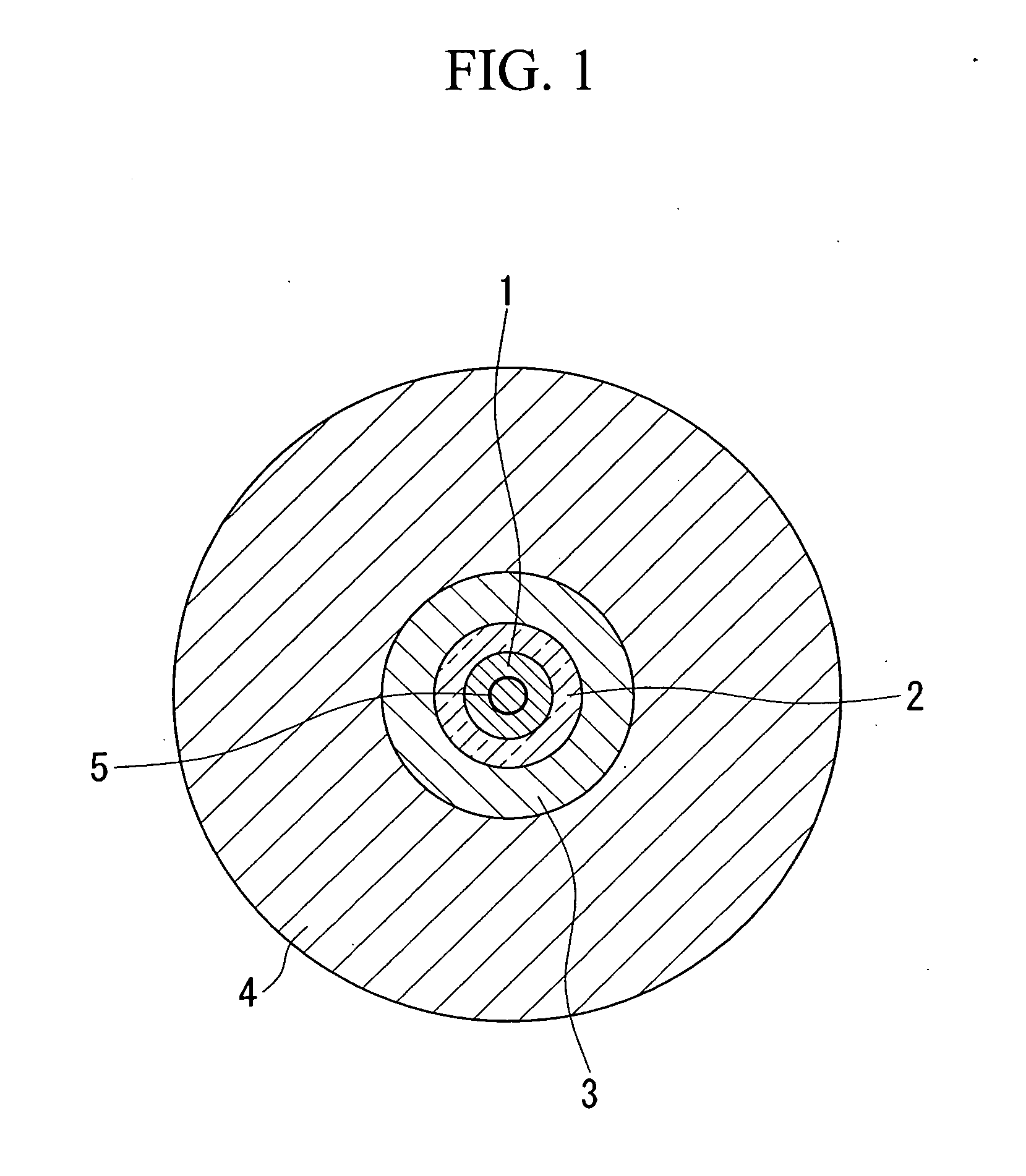
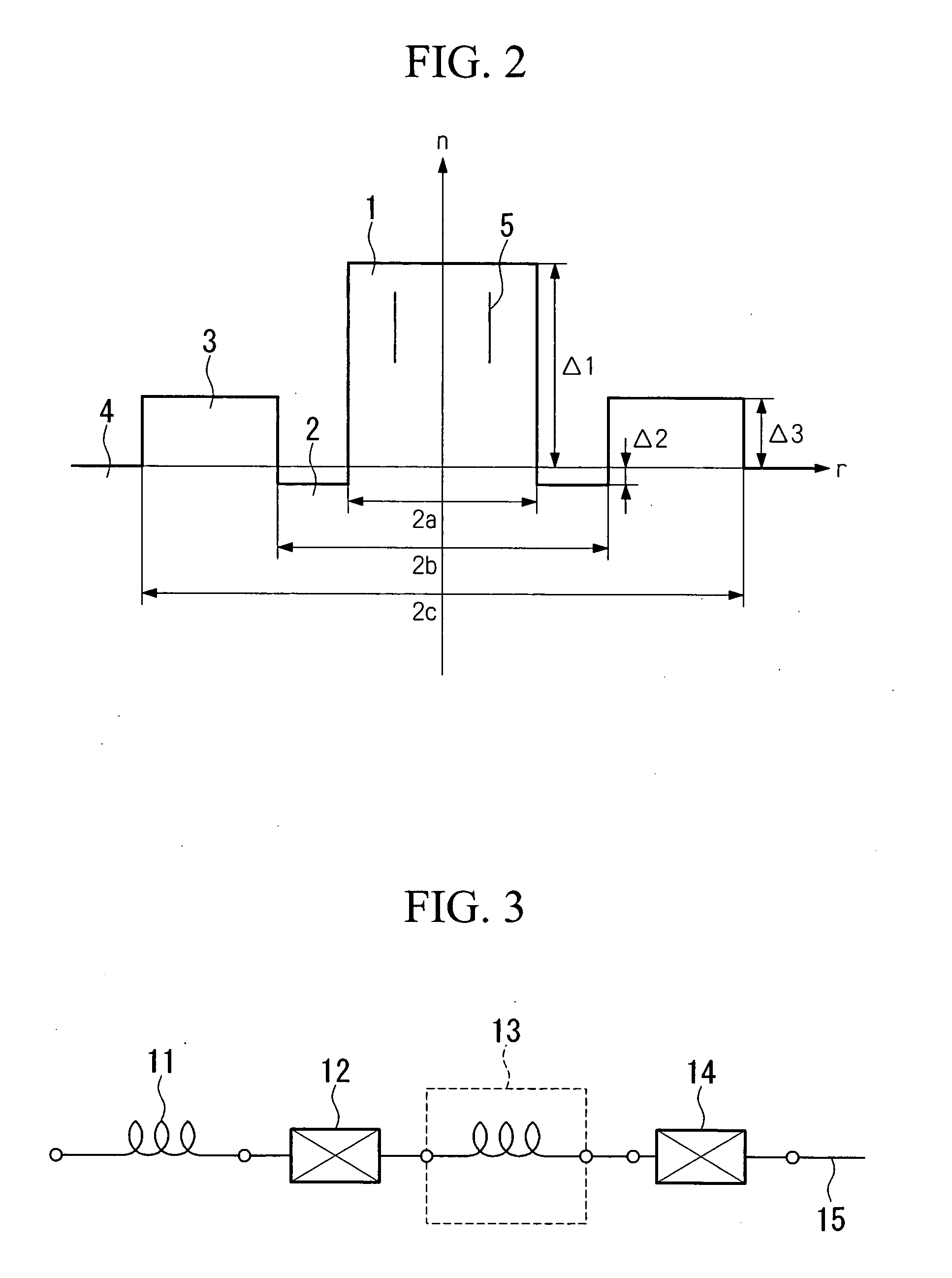
TABLE 1Example 1Example 22a(μm)8.368.402b(μm)14.6014.502c(μm)27.0026.00Δ10.02270.0181Δ2−0.00200.0000Δ30.00770.0039

[0122] In FIG. 5 showing the electric field distribution of the LP02 mode, a loss layer was provided at the position where the electric field becomes zero in the electric field distribution profile, at a radial distance of 2.20 μm from the cente...

example 2

[0128] A higher order mode dispersion compensating fiber having the structural parameters shown in Example 2 of Table 1 was fabricated by modified chemical vapor deposition. This dispersion compensating fiber could propagate the LP01, the LP02, and the LP03 modes. The electric field distribution in the LP01 mode is shown in FIG. 9, the electric field distribution in the LP02 mode in FIG. 10, and the electric field distribution in the LP03 mode is in FIG. 11.

[0129] The dispersion characteristic in the LP02 mode is shown in FIG. 12. As can be seen in FIG. 12, the dispersion at a wavelength of 1.55 μm is approximately −440 ps / nm / km.

[0130] In FIG. 10 showing the electric field distribution of the LP02 mode, a loss layer was provided at the position where the electric field becomes zero in the electric field distribution profile, at a radial distance of 2.30 μm from the center. The loss layer was formed by doping 7.6 mole % of boron trioxide into germanium-doped silica of which the cen...

example 3

[0186] A higher order mode dispersion compensating fiber having the structural parameters shown in Example 3 of Table 4 was fabricated by modified chemical vapor deposition. This dispersion compensating fiber could propagate the LP01, the LP02, and the LP03 modes. The dispersion characteristics in the LP02 mode are shown in FIG. 17. As can be seen in FIG. 17, the dispersion at a wavelength of 1.55 μm is approximately −1200 ps / nm / km.

TABLE 4Example 3Example 42a(μm)8.368.402b(μm)14.6014.502c(μm)27.0026.00Δ10.02270.0181Δ2−0.00200.0000Δ30.00770.0039

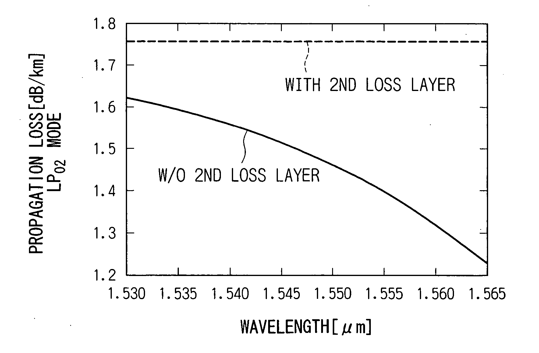
[0187] In this dispersion compensating fiber, first and second loss layers were provided by the following procedure. The first loss layer was formed at a radial distance of 2.20 μm from the center by doping 16.8 mole % of boron trioxide (B2O3) into germanium-doped silica of which the central core region is made with a thickness of 0.2 μm and A1 of 155 dB.

[0188] The second loss layer was formed at a radial distance of 8.49 μm from the center...


PUM


Abstract

A higher order mode dispersion compensating fiber includes an optical fiber and a first loss layer which is provided within the fiber and which attenuates a lower order mode propagating through the optical fiber while not attenuating a higher order mode which is higher than the lower order mode. A dispersion compensating fiber mode converter for a higher order fiber includes a single mode fiber; a higher order mode dispersion compensating fiber; and a fused and extended portion which has been formed by fusing and extending the single mode fiber and the higher order mode fiber. The fused and extended portion converts between the LP01 mode of the single mode fiber and the LP02 mode of the higher order mode dispersion compensating fiber.

Description

BACKGROUND OF THE INVENTION [0001] Priority is claimed on Japanese Patent Application No. 2003-173422, filed Jun. 18, 2003, the content of which is incorporated herein by reference. [0002] 1. Field of the Invention [0003] The present invention relates to a higher order mode dispersion compensating fiber, more specifically, to a dispersion compensating fiber which reduces interference between lower and higher order modes (multipass interference: MPI) and diminishes wavelength dependence of the propagation loss in higher order modes. In addition, this invention relates to a mode converter for a higher order fiber for converting between a fundamental and a higher order mode in a wider band with low loss, and can be applied to a higher order mode dispersion compensating fiber module, etc. [0004] 2. Description of Related Art [0005] The rapid increase in demand for data communications has created the need for an optical fiber transmission system which can transmit a larger volume of data...

Claims


Application Information

Patent Timeline
Patent Type & Authority Applications(United States)
IPC IPC(8): G02B6/02G02B6/036G02B6/14G02B6/28G02B6/287G02B6/34
CPCG02B6/02261G02B6/03627G02B6/2835G02B6/14G02B6/268G02B6/03644
Inventor GUAN, NINGAIKAWA, KAZUHIKOIKEDA, MASASHIHIMENO, KUNIHARUHARADA, KOICHI
Owner THE FUJIKURA CABLE WORKS LTD
Why Eureka
Try Eureka