Thermal barrier coating with stabilized compliant microstructure

a technology of microstructure and thermal barrier coating, which is applied in the direction of liquid fuel engine components, magnetic recording, record information storage, etc., can solve the problems of increasing heat transfer into the component, unable to operate at increasingly high gas temperature within the engine, and no longer suitable for layering

Active Publication Date: 2005-01-20
HONEYWELL INT INC
View PDF24 Cites 71 Cited by
  • Summary
  • Abstract
  • Description
  • Claims
  • Application Information

AI Technical Summary

Benefits of technology

[0010] The segmentation gaps are interspersed with, and define, a plurality of columns within the first and second segmented columnar ceramic layers. A structure-stabilizing material is disposed within the segmentation gaps. The structure-stabilizing material maintains the integrity of the plurality of columns within the first and second columnar ceramic layers. An outer, continuous, non-segmented ceramic sealant layer is disposed on the second columnar ceramic layer to prevent penetration of extraneous materials into the segmentation gaps.

Problems solved by technology

However, the ability to operate at increasingly high gas temperatures within the engine is limited by the ability of the superalloy components to maintain their mechanical strength and integrity following continued exposure to the heat, oxidation, and corrosive effects of the impinging gas.
However, following exposure to temperatures in excess of about 2000° F., sintering of the multi-grained columns or columnar grains may close segmentation gaps between the columns.
Once the gaps become closed, the ceramic layer can no longer accommodate the large ceramic-substrate thermal expansion mismatch, and the thermal barrier coating tends to spall leading to increased heat transfer into the component.
However, the solubility of alumina in zirconia, or the melting of alumina and zirconia, limits the maximum temperature capability of such thermal barrier coatings to about 3000° F. In contrast, more advanced gas turbine engines require significantly higher surface temperature capability, namely up to about 3400° F.

Method used


Image

  • Thermal barrier coating with stabilized compliant microstructure
  • Thermal barrier coating with stabilized compliant microstructure
  • Thermal barrier coating with stabilized compliant microstructure

Examples


Embodiment Construction

[0018] The following detailed description is of the best currently contemplated modes of carrying out the invention. The description is not to be taken in a limiting sense, but is made merely for the purpose of illustrating the general principles of the invention, since the scope of the invention is best defined by the appended claims.

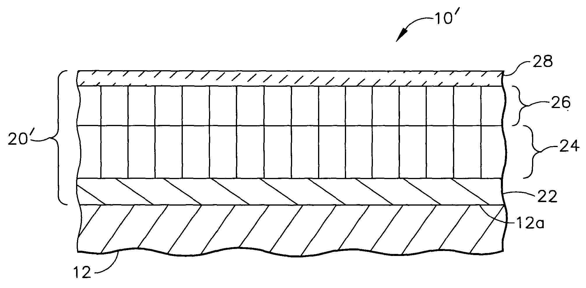
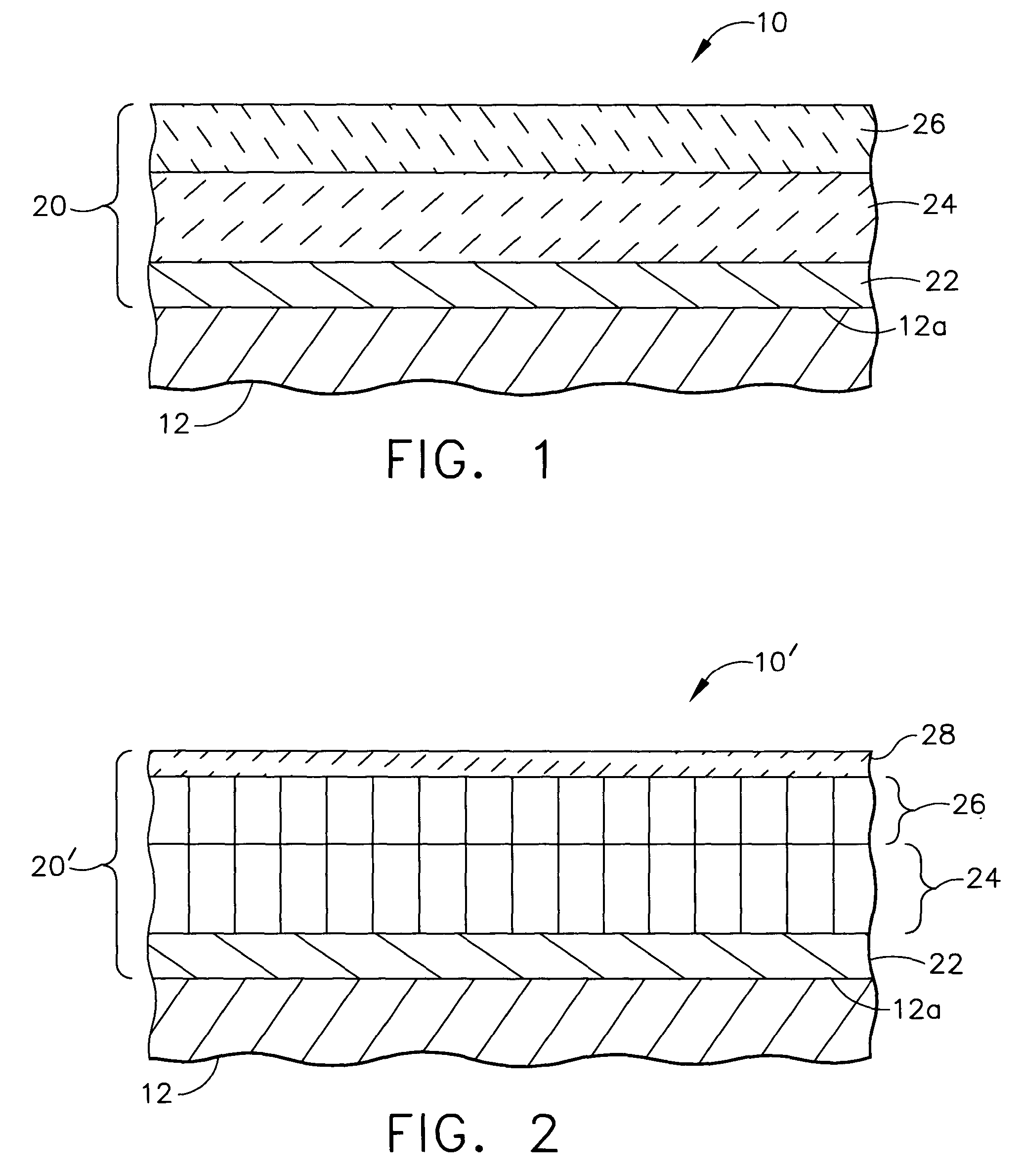
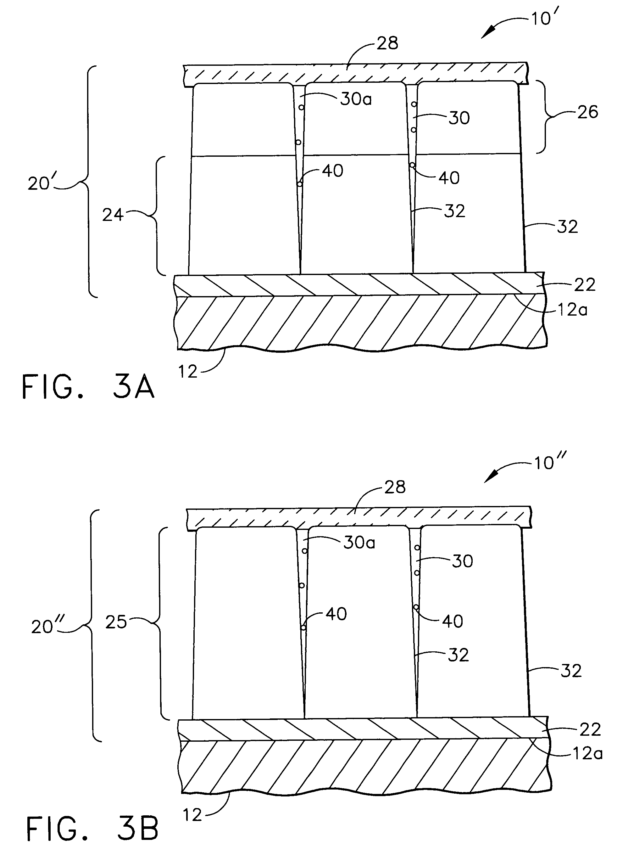
[0019] The present invention generally provides thermal barrier coating compositions, articles of manufacture, and methods for preparing thermal barrier coated components for advanced gas turbine engines. For example, the present invention generally provides a thermal barrier coating for gas turbine components, such as combustors, liners, shrouds, and airfoils. Thermal barrier coatings of the invention have a columnar microstructure comprising at least one segmented columnar ceramic layers, in which the hottest, outer columnar ceramic layer may comprise yttria stabilized hafnia, and a high melting temperature structure-stabilizing material deposited i...


PUM

PropertyMeasurementUnit
temperatureaaaaaaaaaa
thicknessaaaaaaaaaa
thicknessaaaaaaaaaa

Abstract

A thermal barrier coating for a gas turbine component includes a bond coating layer, at least a first segmented columnar ceramic layer on the bond coating layer, and a particulate structure-stabilizing material disposed within a plurality of segmentation gaps within the columnar ceramic layer(s). The thermal barrier coating may further comprise, a second segmented columnar ceramic layer of yttria stabilized hafnia on the first segmented columnar ceramic layer, and an outer, continuous, non-segmented sealant layer covering the yttria stabilized hafnia layer to prevent ingress of extraneous materials into the segmentation gaps. Methods for depositing a thermal barrier coating on a substrate are also disclosed.

Description

BACKGROUND OF THE INVENTION [0001] The present invention generally relates to a thermal barrier coating for a gas turbine component, and more specifically to a thermal barrier coating having at least one ceramic layer having a segmented columnar microstructure and exhibiting increased stability. The present invention also relates to methods for coating a substrate with a thermal barrier coating having at least one segmented columnar ceramic layer. [0002] In order to increase the efficiency of gas turbine engines, higher operating temperatures are now being used. However, the ability to operate at increasingly high gas temperatures within the engine is limited by the ability of the superalloy components to maintain their mechanical strength and integrity following continued exposure to the heat, oxidation, and corrosive effects of the impinging gas. It is known in the art to apply a protective thermal barrier coating to superalloy substrates to provide thermal insulation of the subst...

Claims


Application Information

Patent Timeline
Patent Type & Authority Applications(United States)
IPC IPC(8): B32B15/04C23C18/12F01D5/28
CPCC23C4/18Y10T428/12611C23C18/1208C23C18/1225C23C18/1254C23C18/1295C23C28/3215C23C28/3455C23C28/36F01D5/288Y02T50/67Y02T50/671F05D2230/90F05D2300/611C23C28/34C23C28/345F05D2230/313Y10T428/12618Y10T428/265C23C18/04Y02T50/60C23C4/00C23C14/08C23C14/24C23C18/12C23C28/04
Inventor STRANGMAN, THOMAS E.
Owner HONEYWELL INT INC
Why Eureka
Try Eureka