Socket for electrical parts

a technology for electrical parts and sockets, applied in the direction of individual semiconductor device testing, coupling device connection, instruments, etc., can solve the problems of reducing the chance of electrical parts being shock, and reducing the test time. , to achieve the effect of reducing the stroke of the handling member, reducing the defect or drawback, and reducing the stroke of the operation member

Inactive Publication Date: 2005-01-20
ENPLAS CORP
View PDF4 Cites 1 Cited by
  • Summary
  • Abstract
  • Description
  • Claims
  • Application Information

AI Technical Summary

Benefits of technology

[0007] An object of the present invention is to substantially eliminate defects or drawbacks encountered in the related art mentioned above and to provide a socket for electrical parts capable of reducing the stroke of a handling member (operation member) with minimum operating force and shortening the time of the performance test while suppressing the shock to the electrical parts.
[0008] Another object of the present invention is to provide a socket for electrical parts capable of flexibly determining the path of the pressing member and thus effectively making the pressing member press the electrical part and retire from its pressing position.
[0009] According to a first aspect of the present invention, a socket for electrical parts includes: a socket body for accommodating an electrical part; a pressing member for pressing the electrical part accommodated in the socket body; an operating member disposed to the socket body so as to move vertically; and a driving mechanism for shifting the pressing member from a pressing position to a retired position in accordance with vertical movement of the operating member. In the socket, the driving mechanism includes a rack disposed to the operating member in the vertical direction, the rack including a rack gear, and a follower gear engageable with the rack gear, the follower gear having a first portion and a second portion, the distance from a rotational pivot to a pitch circle of the follower gear being longer at the first portion than at the second portion. Furthermore, when the operating member is depressed, the first portion of the follower gear is engaged with the rack gear. Thus, when the electrical part is pressed, the leverage is increased so that the pressing force to the electrical part is increased. When the electrical part is not pressed, the leverage remains small. Furthermore, shock is suppressed in the electrical part, and the operating member has a small stroke. Also, a test time can be shortened.

Problems solved by technology

Therefore, as the rotation speed of the rack and pinion increases, the test time can be shortened but the chance of giving a shock to the electrical part might increase at the time of pressing.
On the other hand, as the rotation speed of the rack and pinion decreases, the chance of giving a shock to the electrical part is diminished but the test time is prolonged.
Therefore, the pressing portion depresses the electrical part obliquely, not perpendicularly, and may thus scratch the upper surface of the electrical part.

Method used


Image

  • Socket for electrical parts
  • Socket for electrical parts
  • Socket for electrical parts

Examples


first embodiment

[0039] [First Embodiment]

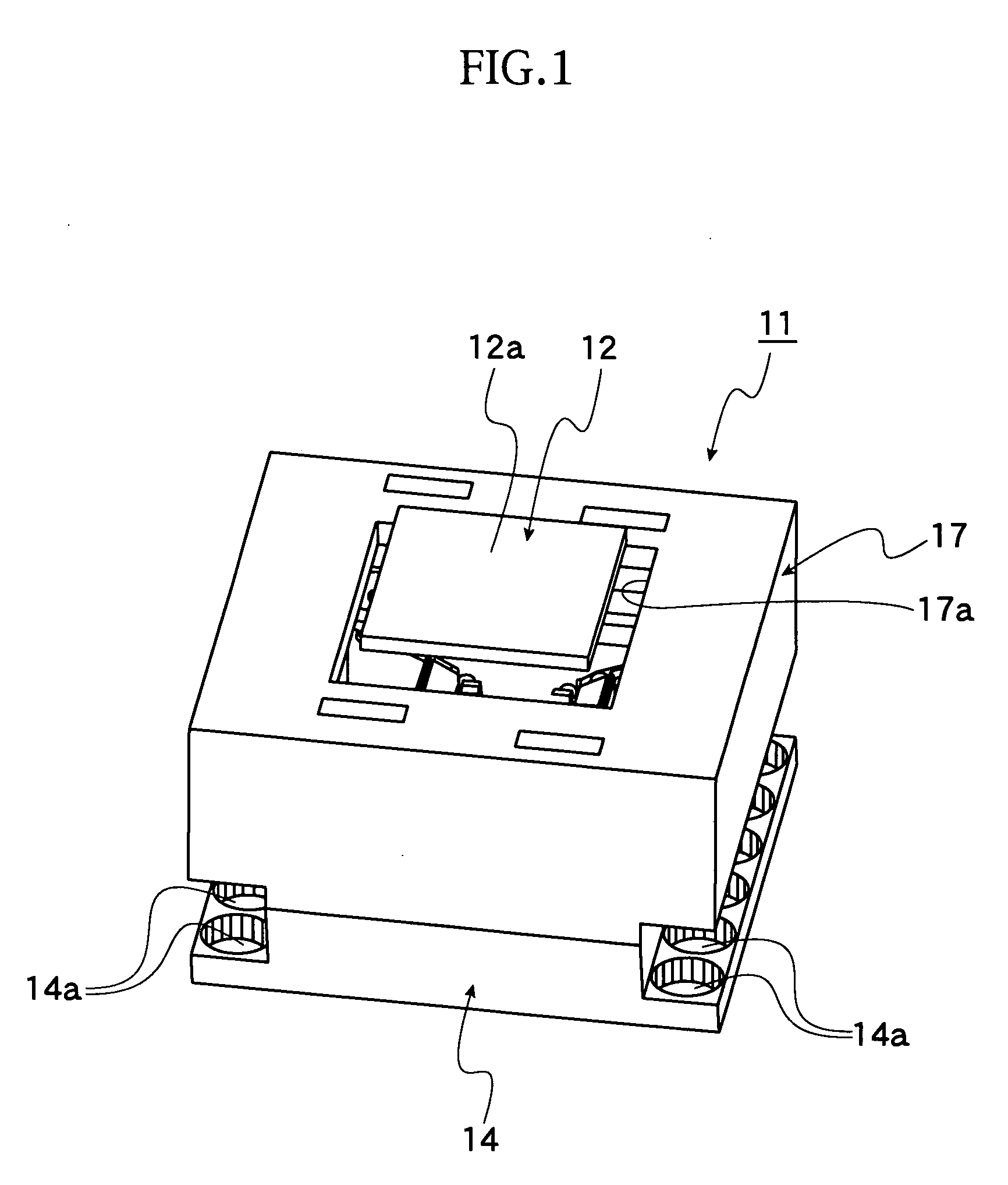
[0040] Referring to FIGS. 1 to 10, a first embodiment of the present invention will now be described. In a performance test of an IC package 12 as an “electrical part”, the IC package 12 is accommodated in an IC socket 11 as a “socket for electrical parts” and is thus electrically connected thereto.

[0041] Referring to FIG. 6, a plurality of solder balls 12b as terminals is disposed at a narrower pitch over the bottom surface of a square package body 12a and is electrically connected to the IC socket 11.

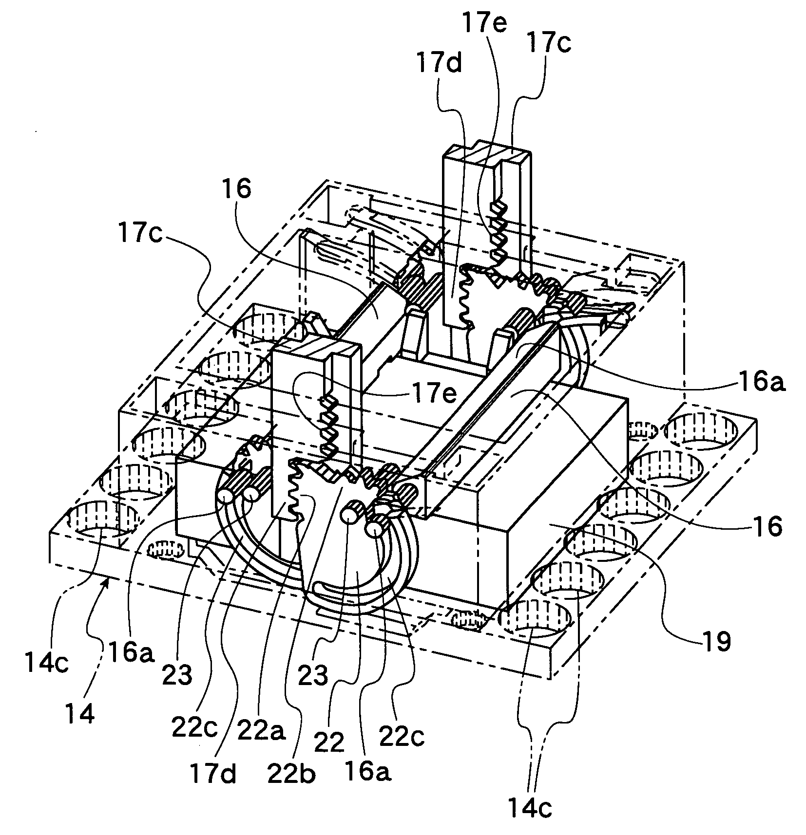
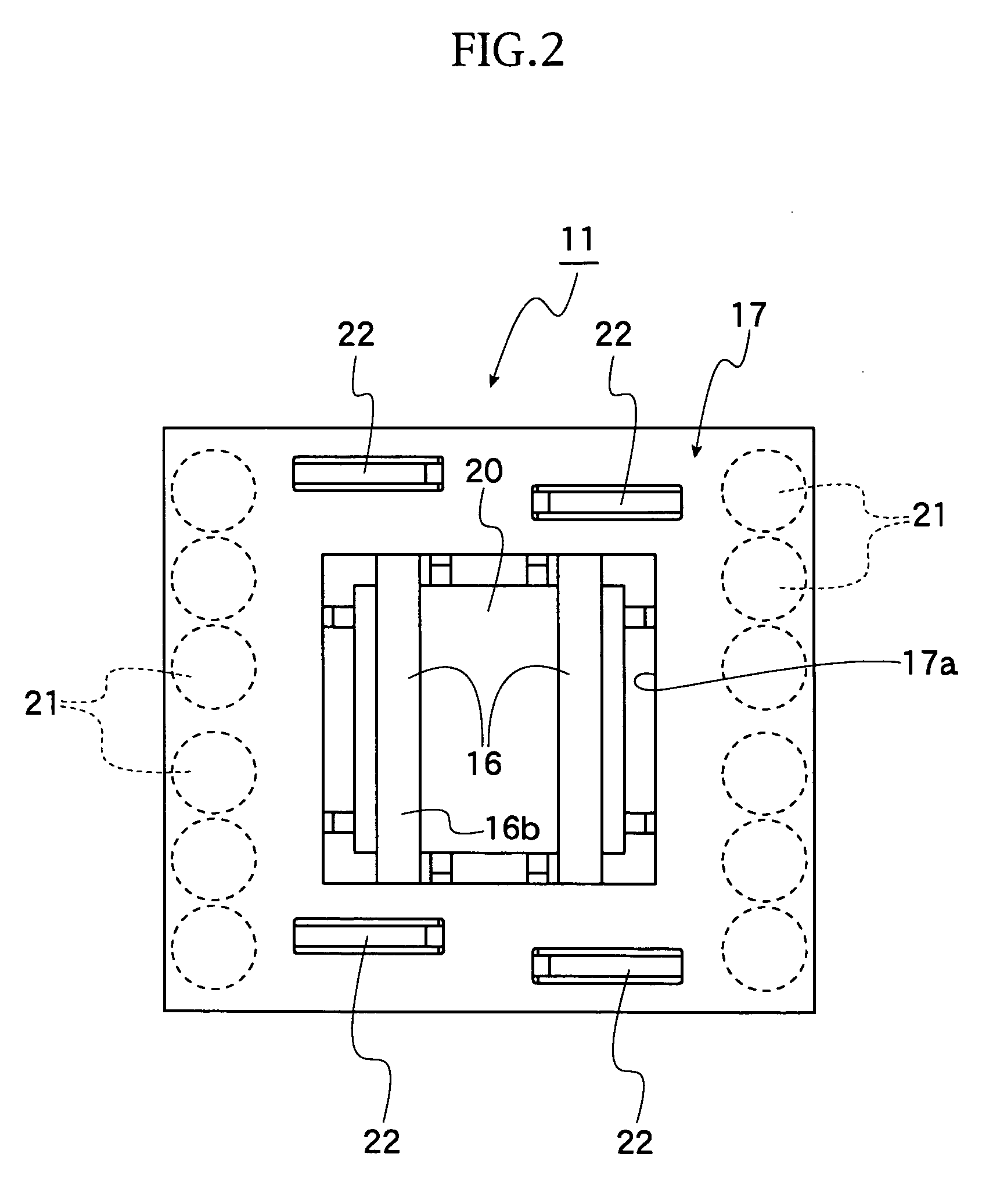
[0042] The IC socket 11 includes a socket body 14, contact pins 15, pressing member 16, an operating member 17, and driving mechanisms. The socket body 14 accommodates the IC package 12. The contact pins 15 are provided in the socket body 14. The pressing members 16 press the IC package 12 accommodated in the socket body 14. The operating member 17 is disposed vertically movable to the socket body 14. The driving mechanisms move the pressing members 16 from ...

second embodiment

[0076] [Second Embodiment]

[0077] A second embodiment of the present invention is illustrated in FIGS. 11 and 12. According to the second embodiment, the pressing member 16 is composed of a material that easily dissipates heat such as aluminum and is provided with a heat sink 16e having a plurality of projections 16d on the top end thereof.

[0078] When the pressing member 16 depresses the IC package 12, heat from the IC package 12 is effectively dissipated through the heat sink 16e. Accordingly, the performance test is appropriately conducted on the IC package 12. Except for these features, the structure and the operation of the second embodiment is the same as those of the first embodiment and therefore the description thereof is not provided here.

third embodiment

[0079] [Third Embodiment]

[0080] A third embodiment of the present invention is illustrated in FIGS. 13 and 14. According to the third embodiment, pressing members 25 are provided in place of the pressing members 16 of the first embodiment. That is, a pair of the pressing members 25 is provided laterally and presses substantially the entire top surface of the IC package 12. In FIGS. 13 and 14, only one of the pressing members 25 is shown.

[0081] Each of the pressing members 25 includes a base end portion 25a and a pressing portion 25c. The base end portion 25a has a base-end-side ellipsoidal opening in cross section. Shafts 26 are fixed to the socket body 14 and each of the shafts 26 is disposed in the base-end-side ellipsoidal opening 25b with a clearance therein. The pressing portion 25c has a pressing-side ellipsoidal opening in cross section, and a driving pin 25e is disposed in the pressing-side ellipsoidal opening 25d such that the driving pin 25e can move therein. The ends of ...


PUM


Abstract

A socket for electrical parts includes driving mechanisms that move pressing members from a depressed position to a retired position when an operating member is vertically shifted. The operating member includes racks each of which has rack gears in the vertical direction. Follower gears engageable with the rack gears are also provided. The follower gears have different distances from the rotational pivot to the pitch circle. When the operating member is depressed, the follower gear with a longer distance from the rotational pivot to the pitch circle is engaged with one of the rack gears.

Description

BACKGROUND OF THE INVENTION [0001] 1. Field of the Invention [0002] The present invention relates to a socket for electrical parts that is used for performance tests on electrical parts such as IC packages. [0003] 2. Related Art [0004] An example of sockets for electrical parts of a known type is described in Japanese Unexamined Utility Model Application Publication No. 7-42063A. According to the description, a semiconductor device is placed on a semiconductor-device-holding plate, and handling member is depressed. In accordance with this downward movement of the handling member, the semiconductor-device-holding plate is shifted outside of the side wall of the socket and thus detached from the semiconductor device. On the other hand, in accordance with the downward movement of the handling member, a pressing member depresses the peripheral portion of the semiconductor device and thus the semiconductor device is fitted on the bottom wall of the socket. [0005] According to such a sock...

Claims


Application Information

Patent Timeline
Patent Type & Authority Applications(United States)
IPC IPC(8): G01R31/26G01R1/04G01R1/073H01R33/76
CPCG01R1/0433H01R33/76
Inventor AZUMI, LEOWATANABE, TSUYOSHI
Owner ENPLAS CORP
Why Eureka
Try Eureka