
Spinal disc prosthesis system

a technology of spine disc and prosthesis, which is applied in the field of spine disc prosthesis, can solve the problems of ineffectively addressing the long-term progressive degeneration of the patient's condition, fusion restricts the range of motion available to the patient, and spinal arthrodesis is associated with premature degeneration of adjacent motion segments

Active Publication Date: 2005-01-20
SPINAL GENERATIONS
View PDF51 Cites 262 Cited by
  • Summary
  • Abstract
  • Description
  • Claims
  • Application Information

AI Technical Summary

Benefits of technology

[0009] The artificial disc prosthesis system is advantageous in that it allows for postoperative removal and replacement of a stabilizing element, such as a fusion prosthesis or a disc prosthesis without the need to remove the entire prosthesis system. In addition, the artificial disc prosthesis system is capable of being adjusted to accommodate stabilizing elements having different shapes and / or sizes. For example, in some embodiments the artificial disc prosthesis system includes a scaffold assembly that leaves the end plates of the vertebrae to which it is attached adequately exposed such that arthrodesis may be performed subsequent to a spinal disc replacement without removing of the entire artificial disc prosthesis system.
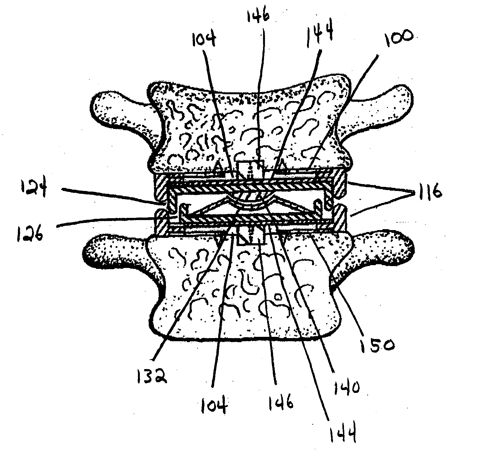
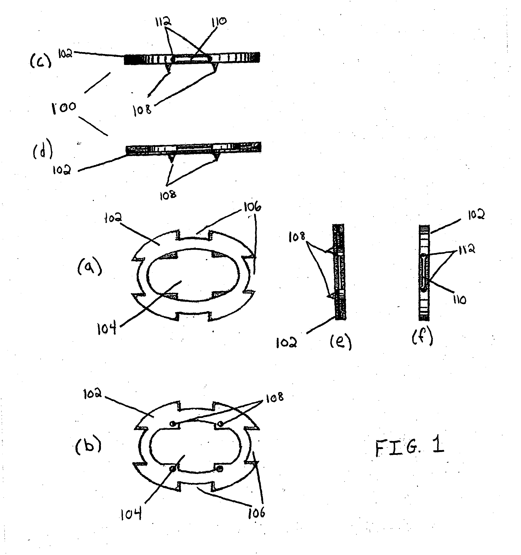
[0012] The scaffold assembly includes at least one base which is attached to the end plate of at least one vertebra defining the intervertebral space. In some embodiments the scaffold assembly includes two bases, one attached to each of the vertebrae that define the intervertebral space. The base(s) may be attached to the end plate(s) using conventional means such as fixation pegs, screws, fixation teeth, and the like. In some embodiments, the size and structure of the base(s) are designed to leave enough of the end plates exposed to allow a fusion prosthesis to be inserted between the vertebrae and fused in place without necessitating the removal of the base(s). For example, the base(s) may be substantially ring-shaped such that, in the absence of a disc prosthesis, enough of the end plates are exposed through the center of the ring(s) to allow a fusion prosthesis to be inserted into the intervertebral space and fused in place through the center of the base(s). It should be noted, that the term “ring-shaped” as used herein is not intended to denote only structures having a cylindrical cross-section, instead any structure may be considered ring-shaped provided it has a peripheral section which defines a central opening. Alternatively, the base(s) may be attached to a central portion of an end plate and may be small enough to leave peripheral potions of the end plate exposed. This design permits a disc prosthesis to be removably disposed around and / or over the base(s). Moreover, this design would enable a suitable fusion prosthesis to be disposed around or over the base(s) and fused to the outer portions of the vertebrae without requiring the base(s) to be removed.
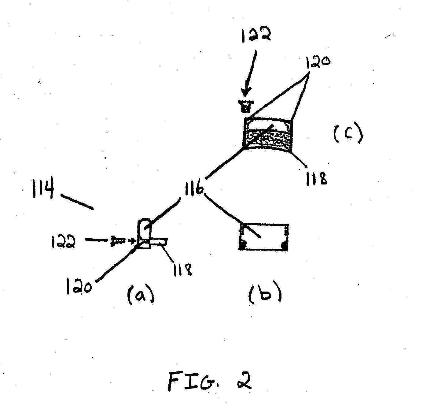
[0014] In other configurations, the prosthetic disc may be removably retained by the scaffold assembly without being rigidly or directly attached to the base of the scaffold. In one such embodiment, the scaffold assembly includes two bases, each attached to one of the vertebrae that define the intervertebral space. In this configuration, the scaffold assembly further comprises one or more appendages attached to one or both bases. Together with the bases, the appendages define a restricted intervertebral space, or “cage,” in which a disc prosthesis may be stably yet removably retained. Using this scaffold design, a stabilizing element could be easily replaced by sliding an old or damaged element out of the cage and sliding a newer or repaired element into the cage without removing the entire scaffold assembly. For example, one or more buttresses may be removably attached to the periphery of one or both bases. The buttresses may extend toward the center of the intervertebral space, such that they define the lateral boundaries of the intervertebral space for a disc prosthesis disposed between the buttresses. The buttresses may be attached to a base using any suitable attachment means, desirably a removable attachment means, including, but not limited to screws, pins, snaps, bands, and the like. The base of the scaffold assembly may be designed such that buttresses may be adjustably attached to the base at different positions and alignments depending on the size and shape of the stabilizing element. This design provides flexibility in the construction of the prosthesis system and allows for disc prostheses having a variety of shapes and sizes to be removably retained by the scaffold assembly. Using this configuration, the disc prosthesis may be inserted into or extracted from the intervertebral space by removing or readjusting one or more of the buttresses on the base to provide an opening into or out of which the disc prosthesis may be inserted or extracted.
[0020] In one embodiment, the disc prosthesis has a nested configuration. In a nested disc prosthesis, the disc prosthesis includes a rotating joint made from two complimentary surfaces, each mounted to one of a pair of reciprocally positioned internal bases or cups. Each of the internal bases or cups is mounted to one of a pair of larger external bases or cups that form an external reciprocal pair. The internal cups may be centered within their respective external cup or they may be offset with respect to the centers of the external cups in order to provide flexibility in the location of the axis-of-motion.

Problems solved by technology

The majority of these problems are related to the spinal discs.
Clinical studies increasingly suggest that while this surgical technique is likely to result in short-term relief, it does not effectively address the progressive degeneration of the patient's condition in the long run.
Fusion restricts the range of motion available to the patient.
Further, spinal arthrodesis is associated with premature degeneration of adjacent motion segments, due to the transference of additional stresses and motion from the immobilized segment to the adjacent unfused levels.
However, a correspondingly successful and safe method and device for spinal arthroplasties has not been developed.
With respect to the latter, which replace only the soft center of the disc while retaining the firmer disc walls, disc spacer devices can restore normal height, but provide no assurance that a proper seal or structural integrity are achieved.

Method used


Image

  • Spinal disc prosthesis system
  • Spinal disc prosthesis system
  • Spinal disc prosthesis system

Examples


Embodiment Construction

[0039] The present invention relates to an artificial disc prosthesis system, a method for revising a stabilizing element using the artificial disc prosthesis system, and a disc prosthesis that may be used in the artificial disc prosthesis system. The artificial disc prosthesis system includes a scaffold assembly adapted to removably receive a stabilizing element, such as a disc prosthesis or a fusion prosthesis and a stabilizing element removably retained by the scaffold assembly. The scaffold assembly may be adjusted to accommodate stabilizing elements having different sizes and shapes. Stabilizing elements may include any element that stabilizes two adjacent vertebrae in a spinal column in the absence of a vertebral disc. Common examples of stabilizing elements include disc prostheses and fusion prosthesis. The disc prosthesis may be of any of a wide variety of known and commercially available disc prostheses designed to simulate spinal motion.

[0040] By providing an adjustable s...


PUM


Abstract

The present invention relates to an artificial disc prosthesis system which includes a scaffold assembly and a fusion or disc prosthesis removably retained by the scaffold assembly. The artificial disc prosthesis system facilitates the removal, replacement or upgrade of disc prostheses without the need to remove the entire system from the intervertebral space in which it is disposed. Also provided are disc prostheses suitable for use in the artificial disc prosthesis system.

Description

FIELD OF THE INVENTION [0001] The present invention relates generally to spinal column intervertebral disc prostheses. BACKGROUND [0002] It is commonly estimated that about 80% of Americans will see a health care professional at some point in their lives for back problems. Many people claim ongoing back pain as a permanent malady. The majority of these problems are related to the spinal discs. For example, about 250,000 Americans each year undergo surgery for herniated discs. [0003] The spinal column is comprised of 26 interlocking vertebrae. These vertebrae are separated by discs. The spine serves two basic functions: (1) it provides load bearing support for one half of the body's mass and (2) it protects the nerves of the spinal column. The discs serve to provide shock absorption as well as to facilitate the bending of the spine. The discs are formed of a cartilaginous outer structure, the annulus fibrosus, with a gel-like inner structure, and the nucleus pulposus. The nucleus pul...

Claims


Application Information

Patent Timeline
IPC IPC(8): A61F2/00A61F2/30A61F2/44
CPCA61F2/4425A61F2310/00239A61F2002/302A61F2002/3024A61F2002/30362A61F2002/30433A61F2002/305A61F2002/30571A61F2002/30604A61F2002/30614A61F2002/30649A61F2002/30772A61F2002/30841A61F2220/0025A61F2220/0033A61F2220/0041A61F2230/0065A61F2230/0069A61F2310/00023A61F2310/00029A61F2310/00203A61F2/4455A61F2002/30235
Inventor SWEENEY, PATRICK J.
Owner SPINAL GENERATIONS
Learn More