Mapping tool graphical user interface

a graphical user interface and mapping tool technology, applied in the field of mapping tools graphical user interfaces, can solve the problems of lack of flexible and rich universal language, and many challenges, and achieve the effect of zooming ou

Inactive Publication Date: 2005-01-20
MICROSOFT TECH LICENSING LLC
View PDF16 Cites 212 Cited by
  • Summary
  • Abstract
  • Description
  • Claims
  • Application Information

AI Technical Summary

Benefits of technology

[0012] The mapper user interface enables a user to graphically construct a translation mapping between a source schema and a destination (target) schema. This provides significant advantages over existing tools and methods which required a user to generate translational script or code. By providing a graphical environment for the creation of translation mappings, business personnel may efficiently generate document mappings without extensive knowledge of programming languages or the assistance of programmers. The user interface itself provides separate display regions or zones for the source and destination objects, which may be graphically presented as tree structures, with a mapping (grid) region in between.
[0017] The interface further provides replacement of the source and / or destination schema trees. This allows a user to correct or modify a previously created schema tree using an editor tool, and to reinsert the modified tree into a mapping without destroying the existing links in the mapping. The user interface re-establishes the links where possible, according to node name recognition or other considerations, and provides indications to the user of links which could not be re-established. In addition, the user interface allows the use of various data sources as source or destination schemas, such as documents, spreadsheets, databases, and other information sources. Translations are provided, whereby the mapper tool user interface generates a tree representation of such information sources for the creation of a mapping therebetween.
[0020] According to another aspect of the invention, the source and target objects may include root nodes, record nodes, and field nodes. The field nodes may be indented in hierarchical fashion from the record nodes, and the record nodes are indented in hierarchical fashion from the root nodes. In addition, the mapping screen region may be located between the source and target screen regions, wherein the indentation of field and record nodes in the source and target screen regions is toward the mapping screen region. This provides an easy to use interface, wherein the hierarchical indentation of the source and target trees provides optimal access to tree nodes from the mapping screen region using a mouse or other user interface selection device.
[0024] According to another aspect of the invention, one or more scrolling indicia may be provided in the mapping screen region adapted to allow the user to selectively display portions of the mapping in the mapping screen region. This allows a user to create a large complex mapping, a portion of which is displayed in the mapping screen region. The scrolling indicia is displayed near an outer perimeter of the mapping region when the user moves a user interface selection device near the outer perimeter. The scrolling indicia indicates a direction in which scrolling is possible, and the mapping screen region may scroll the mapping display in the direction indicated by the scrolling indicia when the user selects the scrolling indicia using the user interface selection device.
[0025] The user interface may further include a mapping preview page in a mapping preview page region adapted to display the entire mapping. This allows a user to effectively zoom out to see an overview of the mapping. The mapping preview page further comprises a current region indicia adapted to indicate the portion of the mapping currently displayed in the mapping screen region. The user may move the current region indicia within the mapping preview page region, to thereby change the portion of the mapping currently displayed in the mapping screen region.
[0026] According to still another aspect of the invention, the user interface may also include a test screen region adapted to display a test target object instance according to the mapping. The test screen region may further comprises a test value page adapted to allow a user to associate a constant value with a node in one of the source object and the target object, and a test output window adapted to display the test target object instance. This allows the user to simulate document translations according to the current mapping in the mapping region.

Problems solved by technology

Building business-to-business (B2B) e-commerce systems presents many challenges to the system architect.
In addition, Internet security issues are involved in business to business data interchange.
Thus, several challenges are faced by businesses, governments, and other entities wishing to interact via electronic documents and other forms of electronic commerce.
The challenges to interaction across business boundaries include lack of a sufficiently flexible and rich universal language to specify, package, publish, and exchange both structured and unstructured information across application or business boundaries, lack of a flexible and rich universal language to specify, package, publish, and execute transformation rules to convert information from one format to the other as application and business boundaries are crossed, and lack of middleware-neutral application level communication protocols to enable automated interactions across application or business boundaries.
However, no single proprietary solution or middleware platform meets all the needs of a complex deployment environment.
In addition, the cost and complexity of integrating together ERP systems, inventory management systems, or sales tracking systems within a single organization strains the capabilities of most large and small companies alike.
Whether the code representing such a mapping is written in XSL or another language, writing this code is difficult and typically beyond the capabilities of ordinary business personnel.
The complexity of such programming languages and the learning curve associated therewith has heretofore discouraged average business personnel from attempting to create document mappings without the aid of experienced programmers.

Method used


Image

  • Mapping tool graphical user interface
  • Mapping tool graphical user interface
  • Mapping tool graphical user interface

Examples


Embodiment Construction

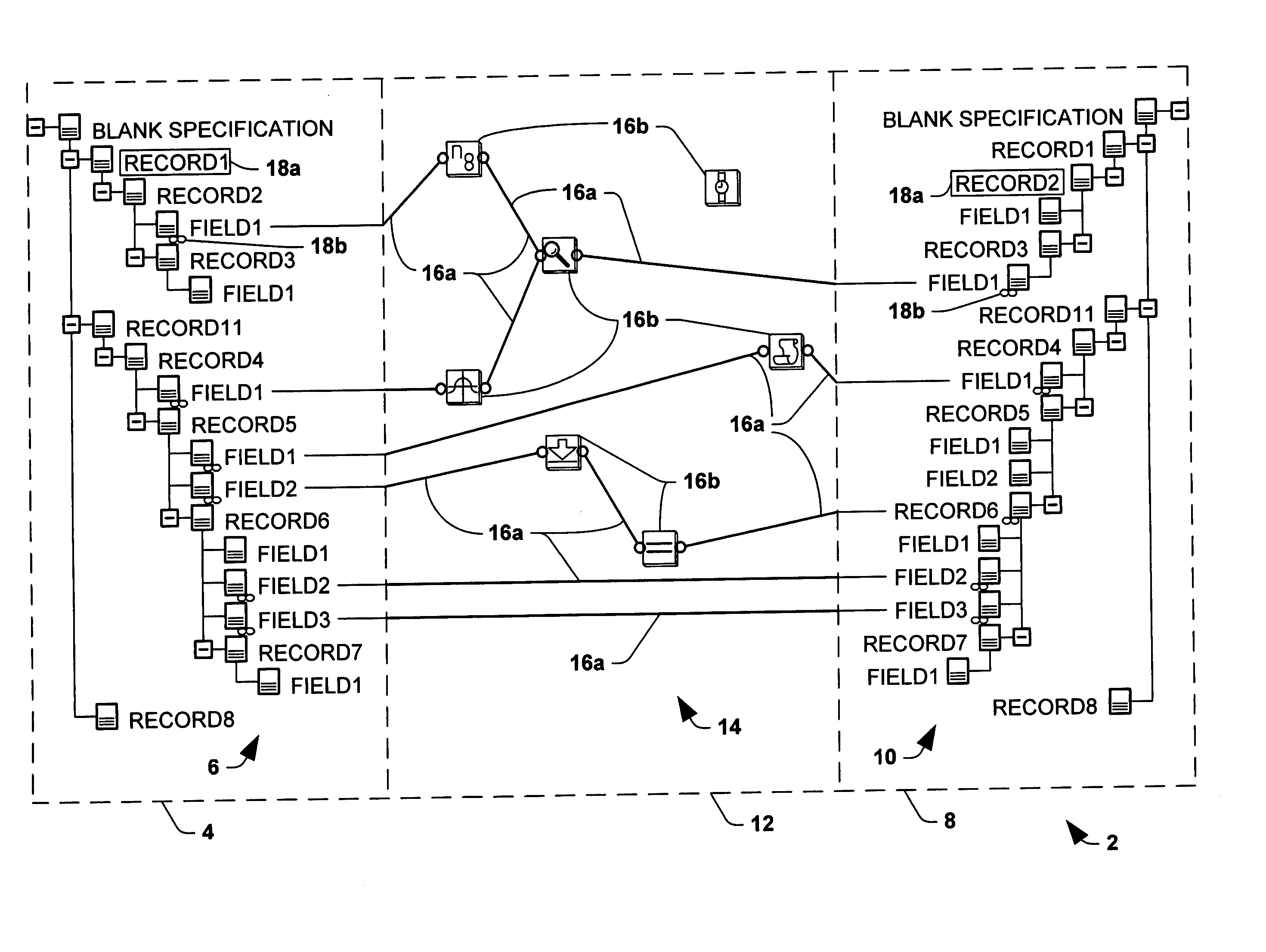
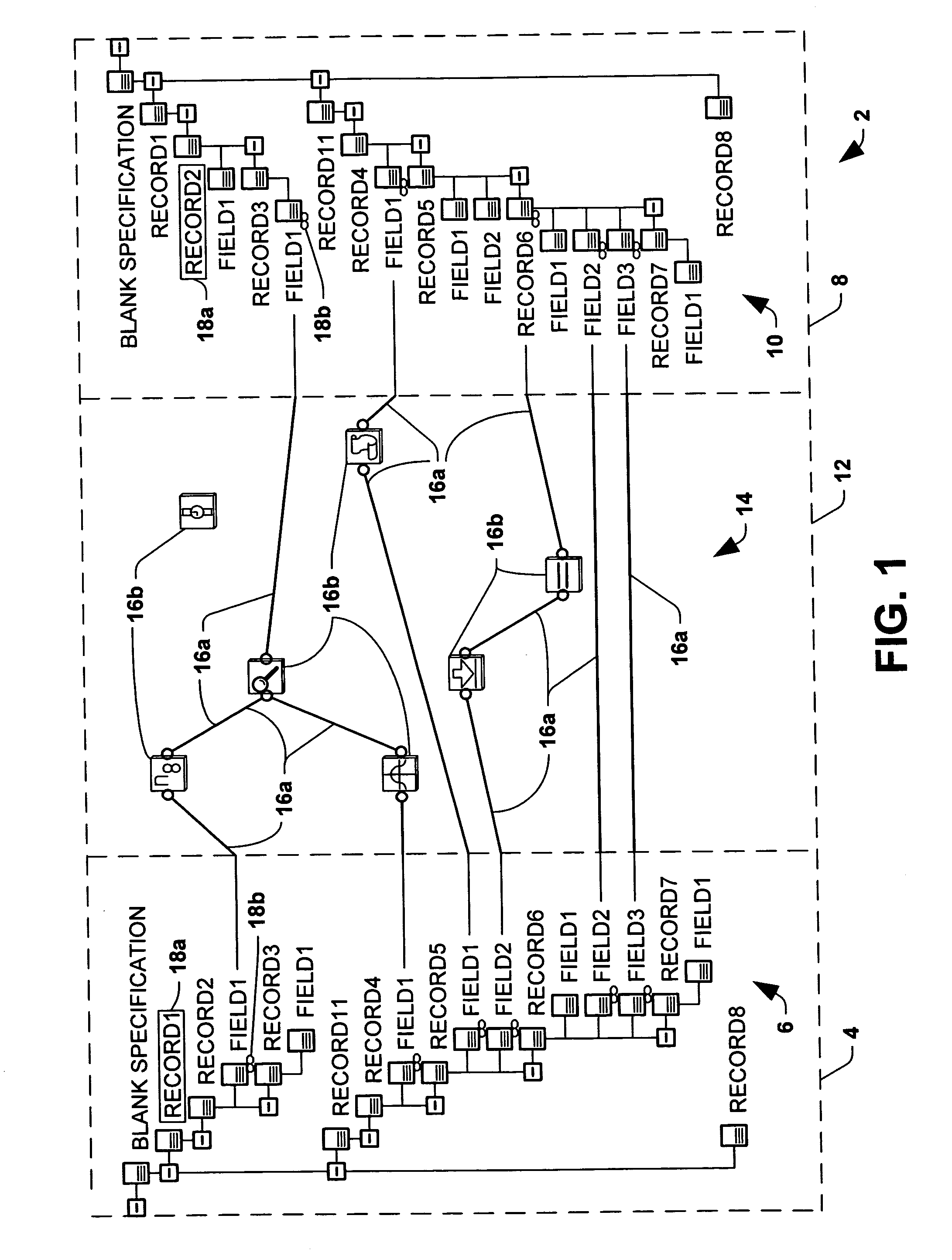
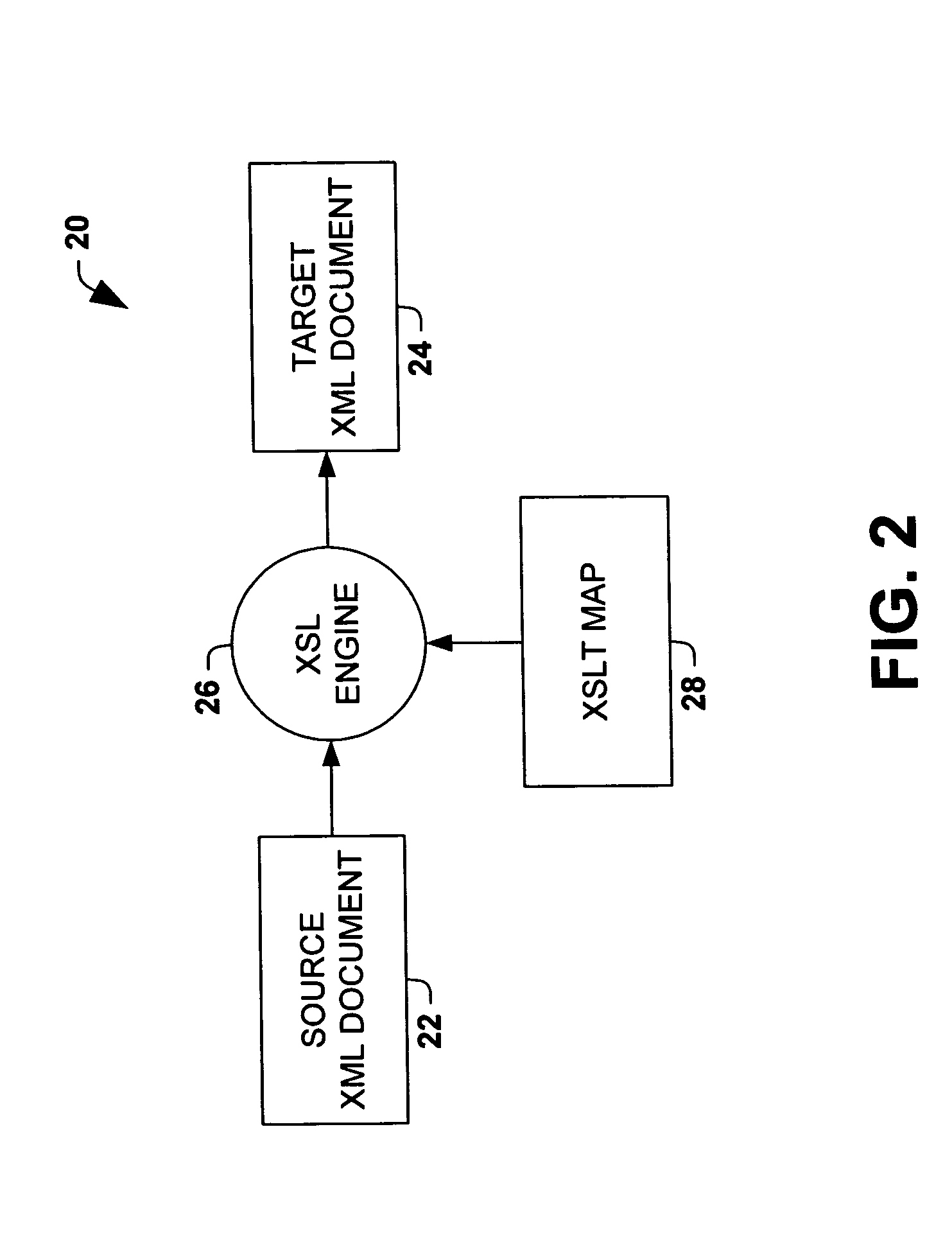
[0067] The following is a detailed description of the present invention made in conjunction with the attached figures, wherein like reference numerals will refer to like elements throughout. According to one aspect of the invention, a method and graphical user interface are provided for creating a mapping between two objects, which may be compiled into output code for use in translating source document information into destination or target document information. The invention thus advantageously allows an unsophisticated to define translational mapping relationships between business documents used across business and / or application boundaries, and to generate code capable of handling the information transfers therebetween, without having extensive knowledge of computer programming languages.

[0068] While some of the implementations and aspects of the invention are illustrated and described hereinafter with respect to source and target objects which are XML schemas, the invention fin...


PUM


Abstract

A graphical user interface and method for creating a mapping between a source object and a destination or target object are provided. The user interface includes a source screen region which displays a graphical representation of a source object, a target screen region which displays a graphical representation of a target object, and a mapping screen region which allows a user to create a mapping between the graphical representation of the source object and the graphical representation of the target object using graphical mapping indicia. The methodology includes displaying a graphical representation of a source object in a source screen region, displaying a graphical representation of a target object in a target screen region, creating a mapping between the graphical representation of the source object and the graphical representation of the target object in a mapping screen region using graphical mapping indicia, and displaying the mapping in the mapping screen region. The source and target objects may be schemas, spreadsheets, documents, databases, or other information sources, and the graphical mapping indicia may include link indicia and / or function objects linking nodes in the target object with nodes in the source object. The mapping may be compiled into code used by a runtime engine to translate source documents into target documents.

Description

CROSS REFERENCE SECTION [0001] This application is a continuation of copending U.S. application Ser. No. 09 / 662,396, filed Sep. 14, 2000, entitled “MAPPING TOOL GRAPHICAL USER INTERFACE”. The aforementioned application is incorporated herein by reference.COPYRIGHT NOTICE [0002] A portion of the disclosure of this patent document contains material which is subject to copyright protection. The copyright owner has no objection to the facsimile reproduction by anyone of the patent document or the patent disclosure as it appears in the Patent and Trademark Office patent file or records, but otherwise reserves all copyright rights whatsoever. TECHNICAL FIELD [0003] The present invention relates to mapping a source object with a target object. More particularly, the invention relates to a graphical user interface and methods for defining a mapping between a source object and a target object in a mapping tool. BACKGROUND OF THE INVENTION [0004] The Internet is enabling businesses to develop...

Claims


Application Information

Patent Timeline
Patent Type & Authority Applications(United States)
IPC IPC(8): G06F7/00G06F9/44G06F9/54G09G5/00
CPCG06F8/34
Inventor VEDULA, NAGENDER P.BHANDARKAR, ADITYA G.SHUKLA, DHARMA K.TAYLOR, WILLIAM R.
Owner MICROSOFT TECH LICENSING LLC
Why Eureka
Try Eureka