Method of storing and transporting wind generated energy using a pipeline system

a pipeline system and wind energy technology, applied in the direction of couplings, fluid couplings, greenhouse gas reduction, etc., can solve the problems of reducing the reliance on oil, such as from foreign sources, becoming an important national issue, and the amount of power that can ultimately be generated, so as to achieve efficient and economic installation of the new pipeline

Inactive Publication Date: 2005-01-27
ENIS BEN M +1
View PDF12 Cites 57 Cited by
  • Summary
  • Abstract
  • Description
  • Claims
  • Application Information

AI Technical Summary

Benefits of technology

[0023] The use of an underground pipeline formed along a planned route has several advantages:
[0024] First, the thermal inertia of the wall thickness of the pipeline, as well as the ground covering the pipe, provides a useful means of absorbing and releasing heat which can be used to prevent the system from freezing during expansion and over-heating during compression.
[0025] Second, by doing the calculations discussed above, the proper amount, size and distance of piping can be used, so that an appropriate system can be laid out from end to end, that is designed efficiently without having to construct additional grids and networks of pipes, or extra storage means.
[0026] Third, where existing roads or easements are available, such as where underground lines, cables, etc., are located, the system preferably utilizes the existing roads, easements and access areas, etc., to more efficiently and economically install the new pipeline.
[0027] Fourth, where abandoned piping systems, such as natural gas lines, sewer lines or other piping are already in existence, the system can economically reuse the existing pipes, in whole or in part, to more economically provide the necessary storage and transportation capacities for the system.

Problems solved by technology

Indeed, reducing reliance on oil, such as from foreign sources, has become an important national issue.
Energy experts fear that some of these resources, including oil, gas and coal, may someday run out.
Because the amount of wind-generated power is a function of the cube of the wind speed, the amount of power that can ultimately be generated at any given time is subject to wind fluctuations and oscillations, which are unpredictable, uncertain and undesirable.
When wind power is supplied to a grid, sudden surges in one area can upset other areas, and can even bring down the entire system in some cases.
Typical wind farm power outputs are often difficult to deal with because of these variances.
Additional problems relating to the peak power sensitivity of the transmission lines can also occur.
Nevertheless, storage of wind-generated energy has presented its own difficulties in terms of cost and effectiveness.
Large high-pressure storage tanks have also been built, but these systems are costly to construct.
The additional problem this has created, however, is that in many cases, these locations are far from existing electrical power grids and communities where power is needed.
Accordingly, there is often the additional problem of getting the power generated by wind to the locations where the power is needed, i.e., through a distribution network of some kind.
In such case, it would be extremely expensive to require power transmission lines to be built to transmit electrical power generated by wind from the source to the user.
In addition, it is often necessary to obtain permission from local communities to install power transmission towers, which are not only unsightly and potentially harmful, but the process of obtaining approval to build them can be time consuming and costly.

Method used


Image

  • Method of storing and transporting wind generated energy using a pipeline system
  • Method of storing and transporting wind generated energy using a pipeline system

Examples


Embodiment Construction

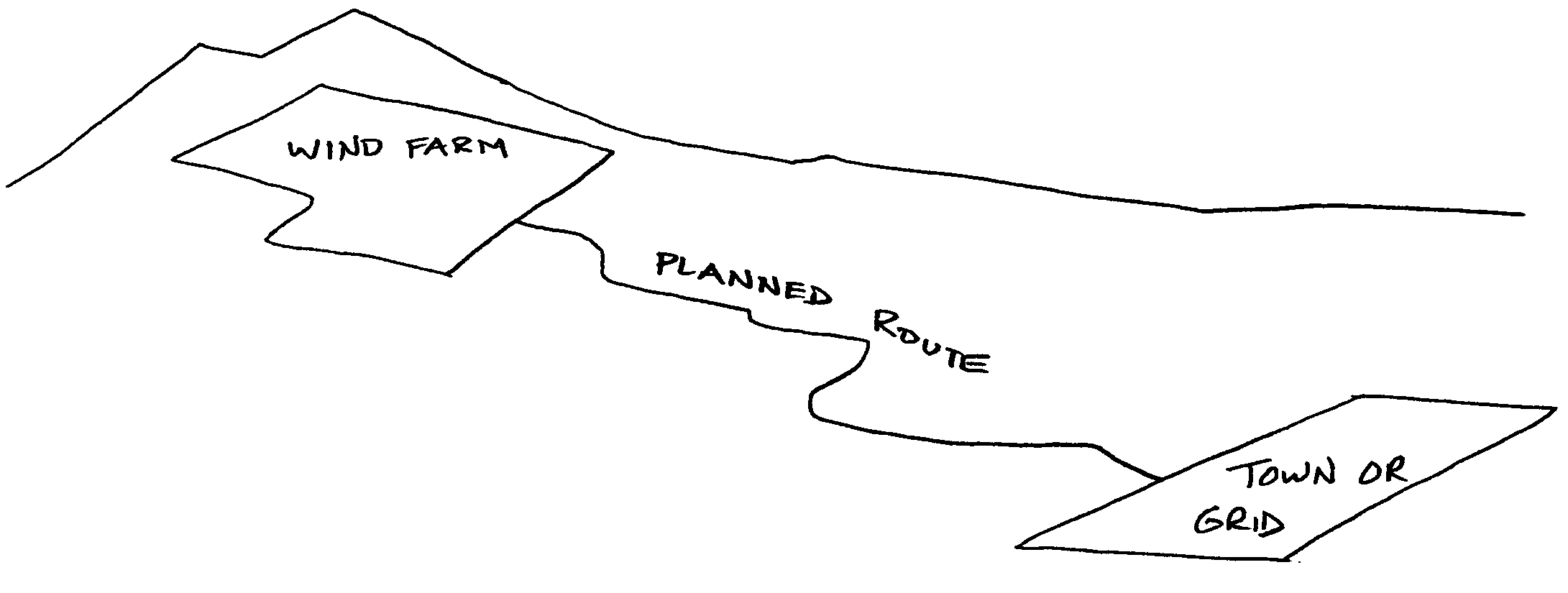
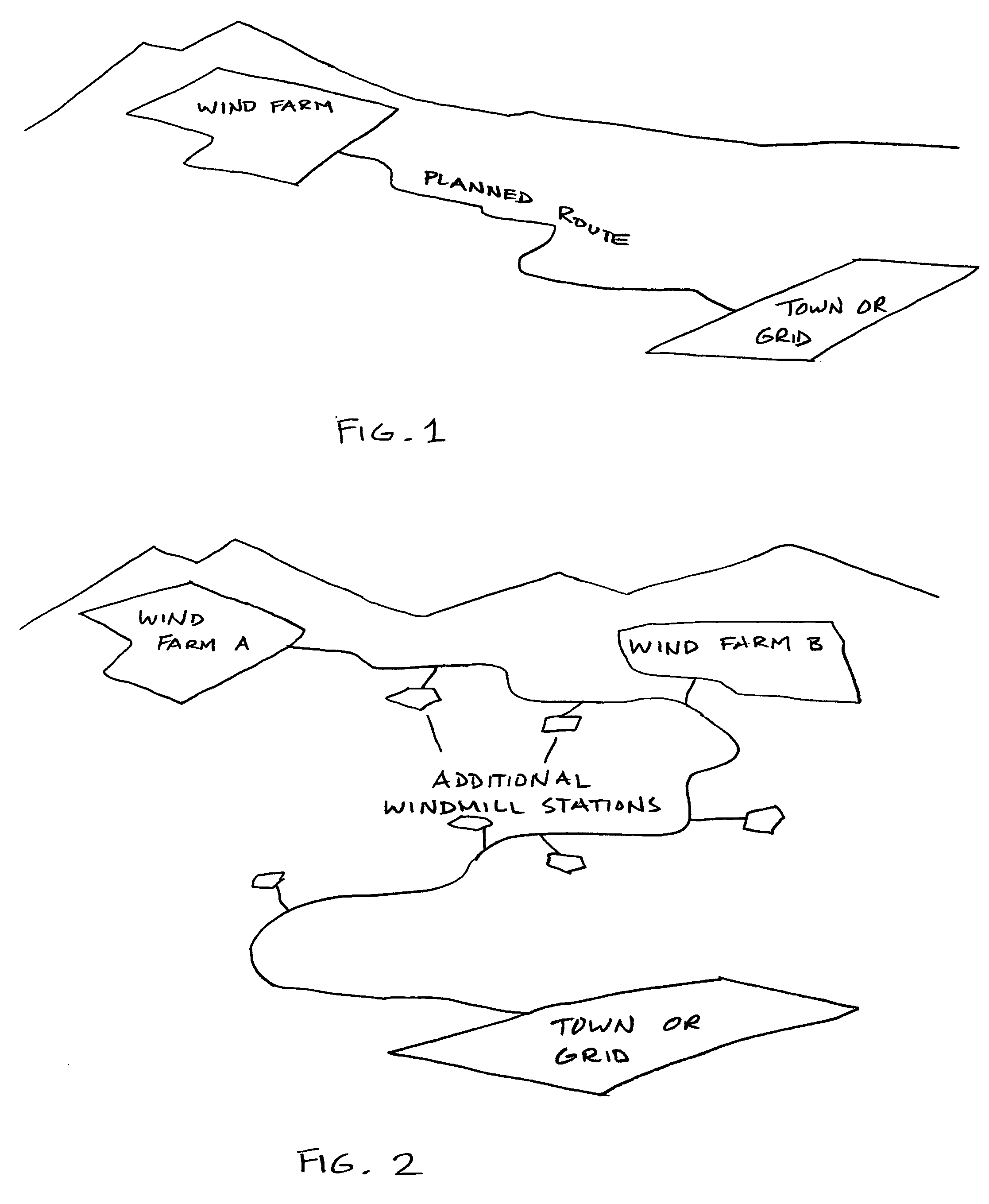
[0030] The present invention relates to wind powered energy generating and storing systems capable of transporting wind generated energy from areas where wind conditions are ideal, to areas where energy is needed, without having to extend lengthy and expensive power transmission lines to grids or communities, and without having to build expensive compressed air storage tanks, etc.

[0031] The present system preferably comprises selecting an area where the wind conditions are likely to be consistent and predictable, or at least more so than other areas that are available, which would be suitable for generating wind energy. By their very nature, these areas are often located in remote areas many miles from communities where people live, and far from existing power grids. They may, for example, be located in deserts, canyons, offshore areas, and on mountain or hilltops far from civilization. They are also often located where property values are relatively low.

[0032] The present method ...


PUM


Abstract

The invention relates to a method of using a pipeline system for storing and transporting compressed air energy generated by wind turbines, wherein the pipeline preferably extends along a predetermined route, between a remote location where wind conditions are relatively consistent and predicable, and a power grid or community needing the power located a distance away. The remote location is preferably provided with a large number of windmill stations for generating electrical and mechanical energy, which is used to compress air into the pipeline. The route is preferably extended along an existing road or easement, and can incorporate abandoned existing piping when available. Turbo expanders and alternators are preferably provided at the user end of the pipeline, to release the compressed air and generate electricity for the grid or community.

Description

RELATED APPLICATION [0001] This application claims priority from U.S. provisional application Ser. No. 60 / 474,551, filed on May 30, 2003.FIELD OF THE INVENTION [0002] The present invention relates to a method of storing and transporting energy, and in particular, to a method of storing and transporting wind generated energy using a pipeline system extended along a predetermined route. BACKGROUND OF THE INVENTION [0003] Generating energy from natural sources, such as from the sun and wind, has been an important objective in this country over the last several decades. Indeed, reducing reliance on oil, such as from foreign sources, has become an important national issue. Energy experts fear that some of these resources, including oil, gas and coal, may someday run out. Because of these concerns, many projects have been initiated in an attempt to harness energy derived from what are called natural “alternative” sources. [0004] While solar power may be the most widely known alternative s...

Claims


Application Information

Patent Timeline
Patent Type & Authority Applications(United States)
IPC IPC(8): F03D9/02F16D31/02F16L
CPCF03D9/028F05B2240/911Y02E60/15Y02E10/725Y02E10/728F05B2240/96F03D9/17Y02E10/72Y02E60/16Y02E70/30F03D9/28F03D9/257
Inventor ENIS, BEN M.LIEBERMAN, PAUL
Owner ENIS BEN M
Why Eureka
Try Eureka