

Front-end integral air-conditioning unit
a front-end, air-conditioning technology, applied in the direction of domestic cooling apparatus, cooling fluid circulation, lighting and heating apparatus, etc., can solve the problems of large amount of time and cost added to the vehicle, large assembly volume, and increased assembly cost, so as to facilitate the installation of the vehicle and reduce the overall packaging
- Summary
- Abstract
- Description
- Claims
- Application Information
AI Technical Summary
Benefits of technology
Problems solved by technology
Method used
Image

Examples
Embodiment Construction
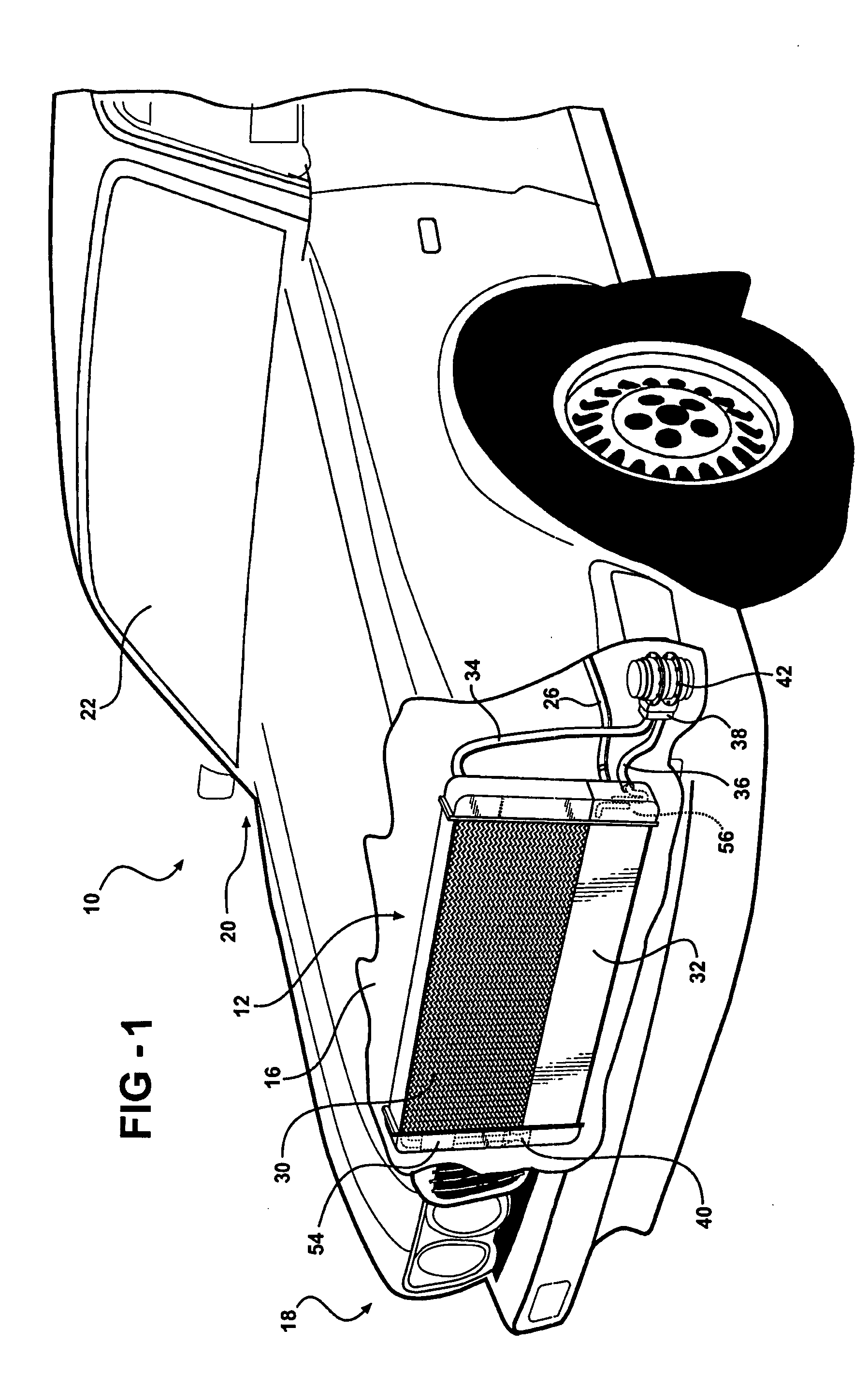
[0021] Referring to the Figures, wherein like numerals indicate like parts throughout the several views, a vehicle is generally shown at 10 in FIG. 1 and comprises a body 22 that defines an engine compartment 16 having a front 18 and a rear 20 disposed in spaced relationship to the front 18 and a passenger compartment 22 that is disposed proximate the engine compartment.
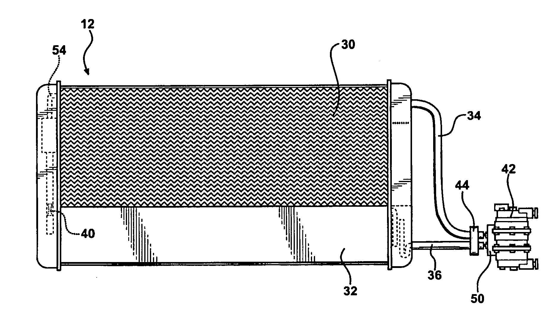
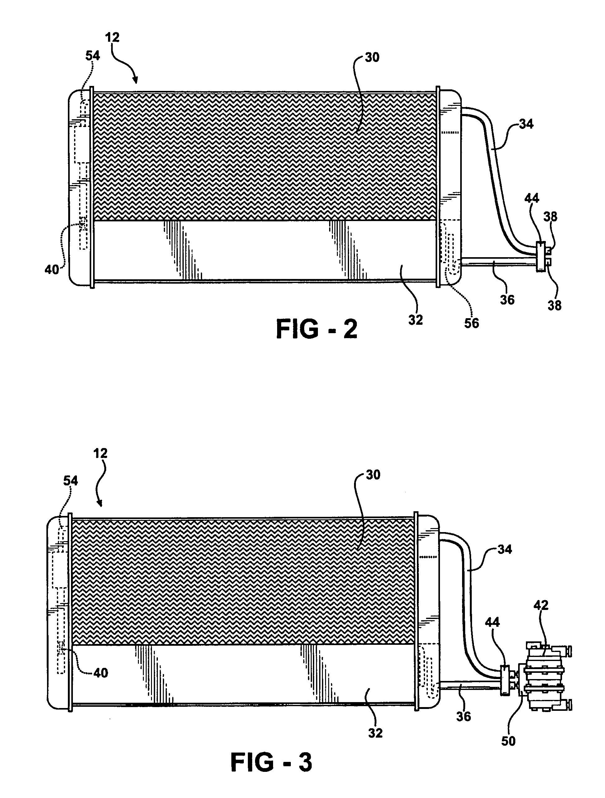
[0022] An air conditioning system is disposed in the vehicle 10 and has two circuits, an air conditioning circuit and a secondary circuit. The air conditioning circuit, shown in FIG. 3, is disposed in the engine compartment 16, preferably at the front 18. The air conditioning circuit comprises a sub-unit 12 and a compressor 42. The sub-unit comprises a condenser 30 that is connected to, and in fluid communication with, a chiller 32. Preferably, the condenser 30 is disposed above the chiller 32. A high pressure fluid line 34 is coupled to the condenser 30, and a low pressure fluid line 36 is coupled to the chiller 32...
PUM
 Abstract
Description
Claims
Application Information