Watercraft canopy

a watercraft and canopy technology, applied in the field of watercraft canopy, can solve the problems of affecting the safety of watercraft, so as to avoid adverse environmental effects on marine vegetation and reduce the deterioration of marine environmen

Inactive Publication Date: 2005-01-27
SUNSTREAM CORP
View PDF21 Cites 27 Cited by
  • Summary
  • Abstract
  • Description
  • Claims
  • Application Information

AI Technical Summary

Benefits of technology

[0009] The present invention provides a watercraft canopy in the form of a substantially translucent cover supported by a semi-rigid framework capable of protecting watercraft from natural elements while allowing a significant amount of sunlight to pass through the canopy. The cover is supported over the watercraft by a metal framework or some other method whereby the cover is semi-rigidly positioned between the sun and the watercraft. The cover will preferably be substantially flexible, and may include a UV-absorbing or reflecting material, the extent of absorption or reflection being selectable according to the intended use, providing protection from UV radiation in the range of 290 to 400 nM. Materials of construction are preferably such that deterioration in a marine environment is significantly reduced. A synth

Problems solved by technology

This has resulted in the exertion of regulatory pressures on those engaged in potentially environmentally impacting activities to avoid actions that may cause adverse impacts to endangered or protected flora, fauna and associated habitat.
A watercraft that is not covered may be subject to damage and degradation and rainwater may enter the watercraft, damaging the interior and potentially overburdening the craft to the point of sinking it: Ultraviolet radiation in the range of 290-400 nM is known to cause a boat's exterior and interior surface paint and materials to degrade.
Prior art, however, does not address recent environmental concerns regarding the use of light-blocking coverings over near-shore marine environments.
Such structures have the di

Method used


Image

  • Watercraft canopy
  • Watercraft canopy
  • Watercraft canopy

Examples


Embodiment Construction

[0021] This section illustrates aspects of the invention, and points out certain preferred embodiments of these aspects. This section is not intended to be exhaustive, but rather to inform and teach the person of skill in the art who will come to appreciate more fully other aspects, equivalents, and possibilities presented by the invention, and hence the scope of the invention as set forth in the claims, which alone limit its scope.

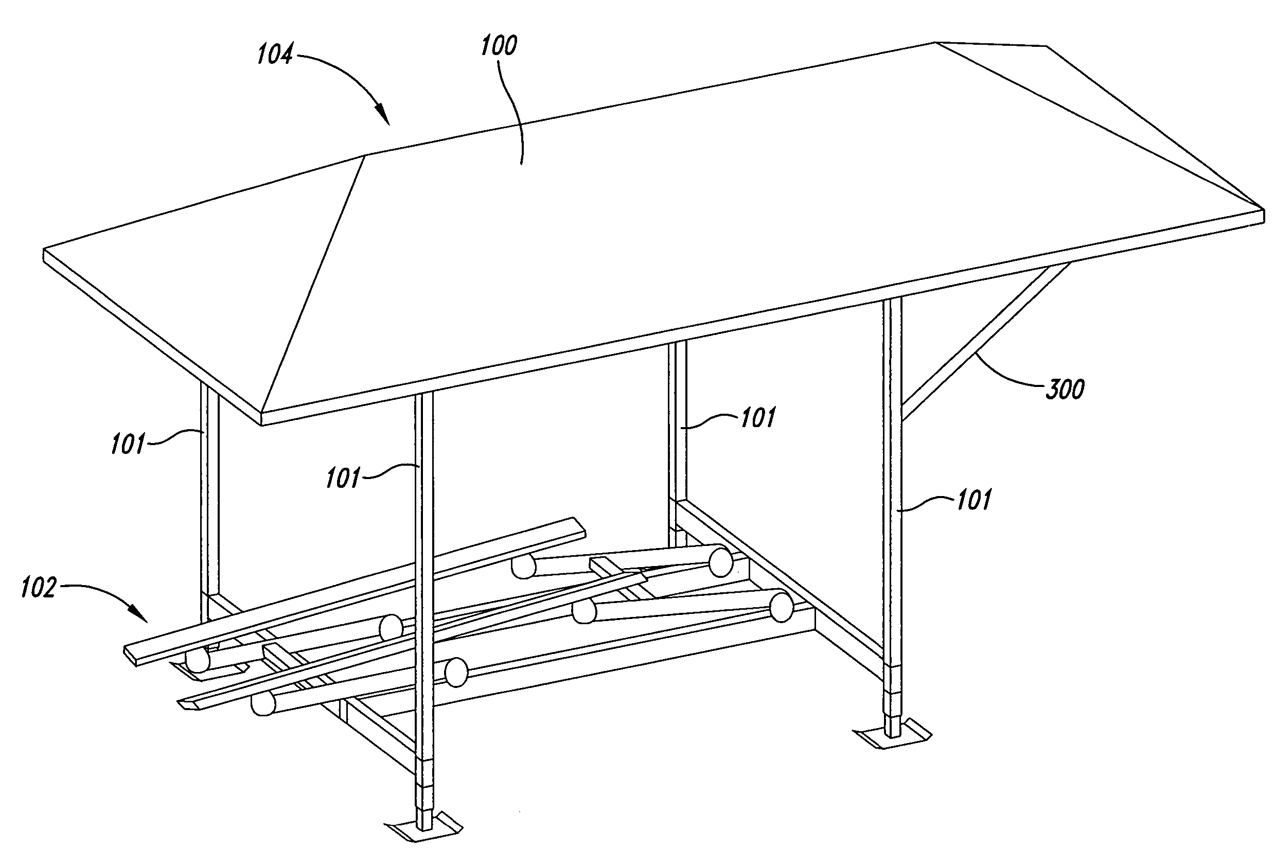
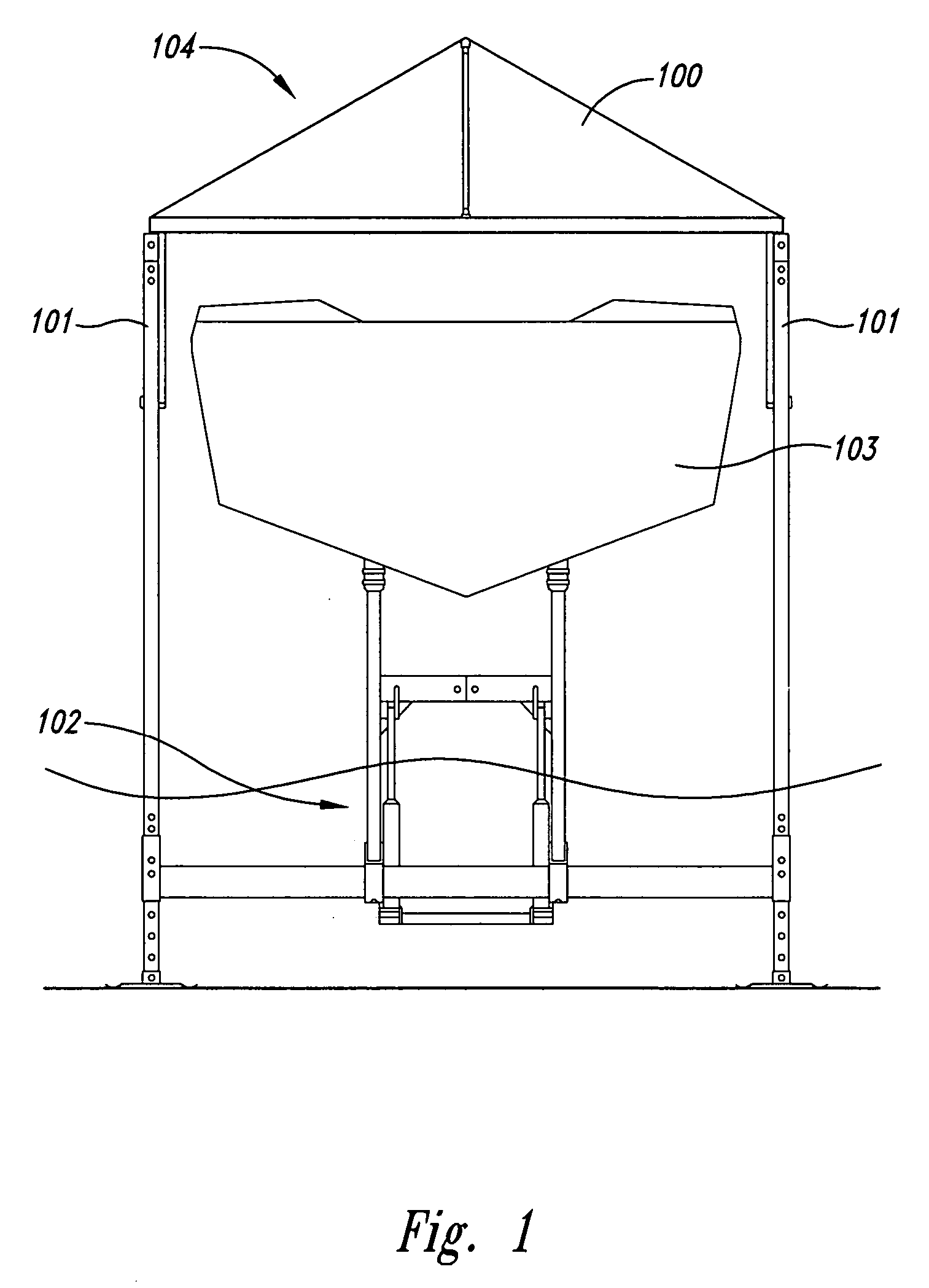
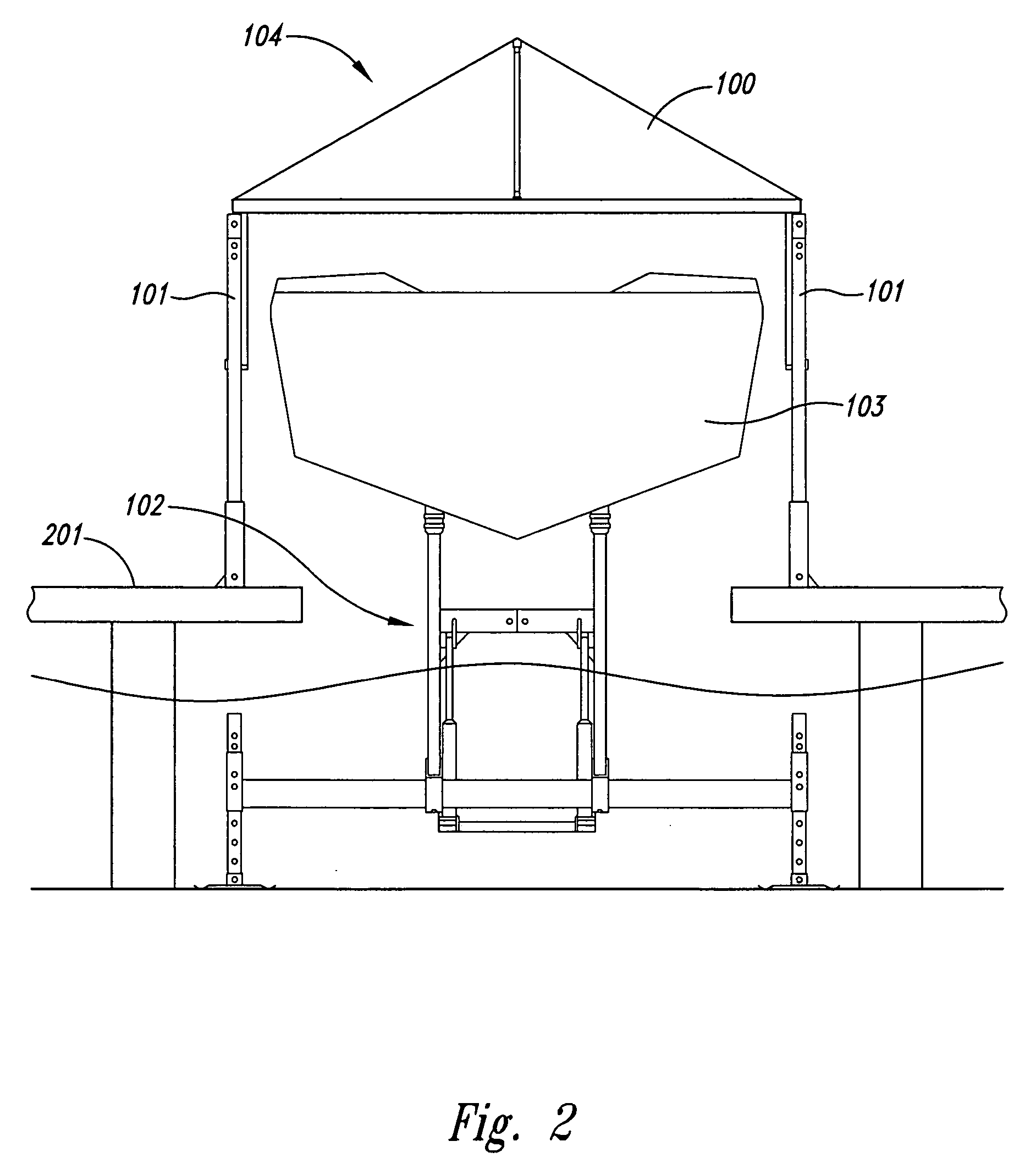
[0022]FIG. 1 shows one embodiment of a watercraft canopy 104 according to the present invention, which includes a thin, flexible, substantially translucent cover 100. The watercraft canopy 104 allows a substantial amount of sunlight to pass through the canopy 104 while also providing protection of a subject watercraft 103 therebelow from the elements. The flexible, substantially translucent cover 100 is positioned between the sun and the watercraft 103 to provide protection from the elements. The cover 100, made rigid or semi-rigid by an interior framewo...


PUM


Abstract

A canopy covering for a watercraft to protect the watercraft from natural elements while allowing a substantial amount of light to be transmitted through the covering so as to not significantly adversely impact the marine habitat below the canopy by light reduction.

Description

BACKGROUND OF THE INVENTION [0001] In recent years, the necessity of avoiding impacts to the natural environment has resulted in the enactment of environmental legislation on the part of Federal and State governments to enhance the quality of the environment by reducing and / or eliminating activities that cause environmentally adverse effects. This has resulted in the exertion of regulatory pressures on those engaged in potentially environmentally impacting activities to avoid actions that may cause adverse impacts to endangered or protected flora, fauna and associated habitat. These pressures have, in turn, brought about the development of a substantial body of environment enhancing, protecting, and impact-minimizing technology. A typical example of a recent, relatively simple device of such technology includes U.S. Pat. No. 6,474,907, which discloses an environmentally compatible archway for road building that is meant to avoid harmful alterations, disruption, or destruction of fis...

Claims


Application Information

Patent Timeline
IPC IPC(8): B63C5/00B63C15/00
CPCB63C15/00B63C5/00B63B17/02
Inventor HEY, KENNETH E.KENLEY, JOHN H.
Owner SUNSTREAM CORP
Why Eureka
Try Eureka