Lithographic apparatus and device manufacturing method

Active Publication Date: 2005-01-27
ASML NETHERLANDS BV
View PDF29 Cites 740 Cited by
  • Summary
  • Abstract
  • Description
  • Claims
  • Application Information

AI Technical Summary

Benefits of technology

This may allow the position of the member above the surface of the substrate to be controlled, in an embodiment, with 3 degrees of freedom, and in an embodiment with 6 degrees of freedom. In an embodiment, the controller is configured to control the actuator to maintain a desired distance between the surface of the substrate and the member. In an embodiment, the controller may also generate a large electronic damping of the member resulting in a design that is less sensitive to vibrations from the liquid supply system. The controller may also be used to effect a real-time monitoring of the quality of a seal, allowing rapid action (e.g. retraction of the member) in the case of a system failure or err

Problems solved by technology

While a gas seal may seal the liquid effectively, it may present further problems.
A relatively high gas pressure is used (with overpressure or gauge pressure relative to the environment of typically 100-1

Method used


Image

  • Lithographic apparatus and device manufacturing method
  • Lithographic apparatus and device manufacturing method
  • Lithographic apparatus and device manufacturing method

Examples


embodiment 1

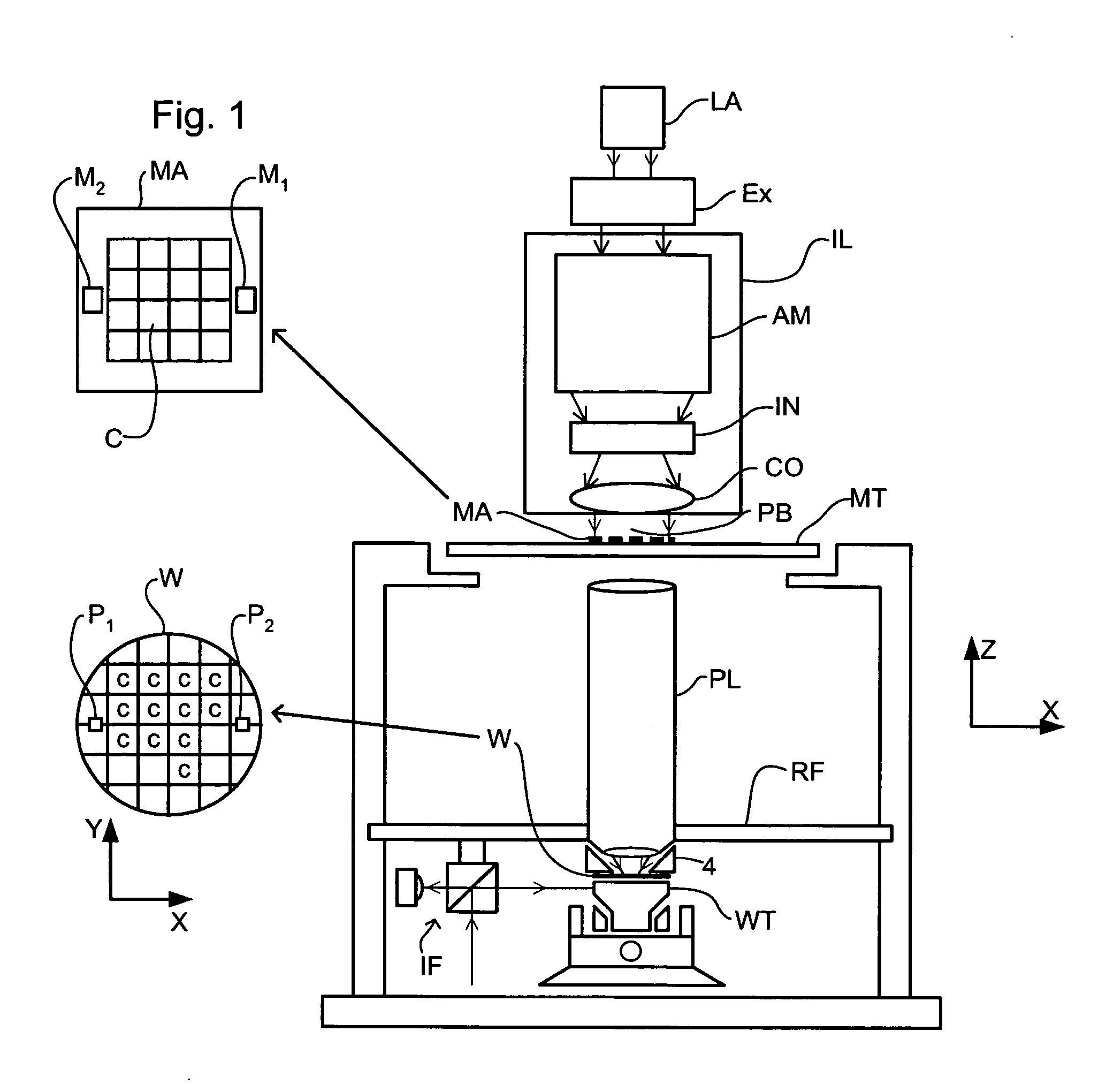
FIG. 1 schematically depicts a lithographic apparatus according to a particular embodiment of the invention. The apparatus comprises: an illumination system (illuminator) IL for providing a projection beam PB of radiation (e.g. UV radiation radiation). a first support structure (e.g. a mask table) MT for supporting a patterning device (e.g. a mask) MA and connected to a first positioning device PM for accurately positioning the patterning device with respect to item PL; a substrate table (e.g. a wafer table) WT for holding a substrate (e.g. a resist-coated wafer) W and connected to a second positioning device PW for accurately positioning the substrate with respect to item PL; and a projection system (e.g. a refractive projection lens) PL for imaging a pattern imparted to the projection beam PB by patterning device MA onto a target portion C (e.g. comprising one or more dies) of the substrate W.

As here depicted, the apparatus is of a transmissive type (e.g. employing a transmi...

embodiment 2

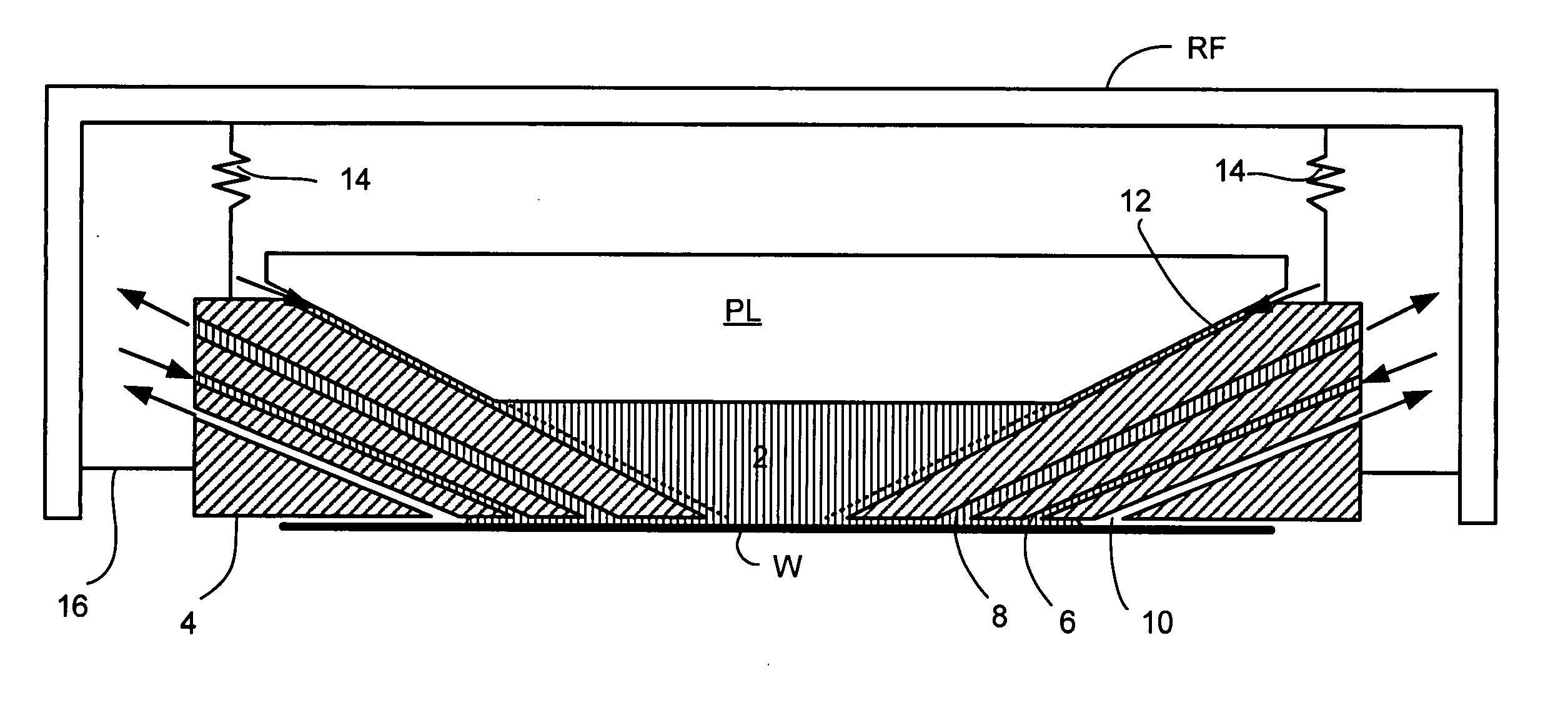
A cross section of a liquid supply system according to a second embodiment of the invention is shown in FIG. 5. The construction of this embodiment is the same as for the first embodiment, save as described below.

In this embodiment a seal member 3 has a single liquid inlet 9. The inlet 9 is located outwards in a radial direction with respect to the optical axis from a liquid filled space 2 between the final element of the projection system PL and the surface of the substrate W. Liquid supplied by the inlet 9 flows both inwards, into the space 2, and outwards towards an outlet 7. The outlet 7 is connected to a low pressure source. The low pressure source causes the liquid to be sucked into the outlet 7 and prevented from entering the rest of the apparatus. A further outlet 11 is provided between the seal member 3 and the projection system PL to remove liquid from the space 2.

In an embodiment, the flow of liquid in the inlet 9 and outlet 11 is a laminar flow to reduce turbulence....

embodiment 3

A cross section of a seal member according to a third embodiment of the present invention is shown in FIG. 6. The construction of this embodiment is the same as for the second embodiment, save as described below.

A seal member 3′ has a liquid inlet 9′ and an outlet 7′ which is connected to a low pressure source. The edges of the outlet 7′ which face the surface of the substrate W are rounded, as is the edge of the seal member 3′ adjacent to the outlet 7′. The rounded edges can have the form of an arc or an arbitrary curved profile. The degree of curvature depends on the dimensions of the inlet / outlet. In this embodiment, the radius of curvature is in the range of 0.1 mm to 5 mm. The rounded edges improve the flow around the edge and reduce turbulence. By replacing the square edges with rounded edges in this manner, the flow of gas and / or liquid through the outlet 7′ is improved.

To further improve the flow through the outlet 7′, a duct or chamber 32 is provided within the seal me...


PUM


Abstract

A lithographic projection apparatus wherein a liquid supply system provides a space between a projection system and a substrate with liquid. The liquid supply system comprises a member. A liquid seal is formed between the member and the substrate by a flow of liquid. In an embodiment, the liquid seal is formed by a flow of liquid from an inlet to an outlet of the member.

Description

This application claims priority from European patent application EP 03254078.3, filed Jun. 27, 2003, which is incorporated herein in its entirety. FIELD The present invention relates to a lithographic projection apparatus and a device manufacturing method. BACKGROUND A lithographic apparatus is a machine that applies a desired pattern onto a target portion of a substrate. Lithographic apparatus can be used, for example, in the manufacture of integrated circuits (ICs). In that circumstance, a patterning device, such as a mask, may be used to generate a circuit pattern corresponding to an individual layer of the IC, and this pattern can be imaged onto a target portion (e.g. comprising part of, one or several dies) on a substrate (e.g. a silicon wafer) that has a layer of radiation-sensitive material (resist). In general, a single substrate will contain a network of adjacent target portions that are successively exposed. Known lithographic apparatus include so-called steppers, in w...

Claims


Application Information

Patent Timeline
IPC IPC(8): G03F7/20H01L21/027
CPCG03F7/709G03F7/70341G03F7/70991
Inventor COX, HENRIKUS HERMAN MARIEDONDERS, SJOERD NICOLAAS LAMBERTUSHOOGENDAM, CHRISTIAAN ALEXANDERKOLESNYCHENKO, ALEKSEY YURIEVICHLOOPSTRA, ERIK ROELOFSANTEN, HELMAR VAN
Owner ASML NETHERLANDS BV
Why Eureka
Try Eureka