Actively quenched lamp, infrared thermography imaging system, and method for actively controlling flash duration

a technology of infrared thermography and active quenching, which is applied in the field of active quenching lamps and infrared thermography imaging systems, can solve the problems of limited analysis of thin objects using ir thermography, early frames must be analyzed and cannot be discarded, and thermal information in the early frames is distorted by the exponential tail of the flash

Inactive Publication Date: 2005-01-27
GENERAL ELECTRIC CO
View PDF49 Cites 30 Cited by
  • Summary
  • Abstract
  • Description
  • Claims
  • Application Information

AI Technical Summary

Problems solved by technology

When imaging thin parts, early frames must be analyzed and cannot be discarded.
However, the thermal information in the early frames is distorted by the exponential tail of the flash because the exponential tail continues to heat the surface of the object during acquisition of the early frames.
Consequently, the analysis of thin objects using IR thermography is currently limited due to the exponential tail of the flash.

Method used


Image

  • Actively quenched lamp, infrared thermography imaging system, and method for actively controlling flash duration
  • Actively quenched lamp, infrared thermography imaging system, and method for actively controlling flash duration
  • Actively quenched lamp, infrared thermography imaging system, and method for actively controlling flash duration

Examples


Embodiment Construction

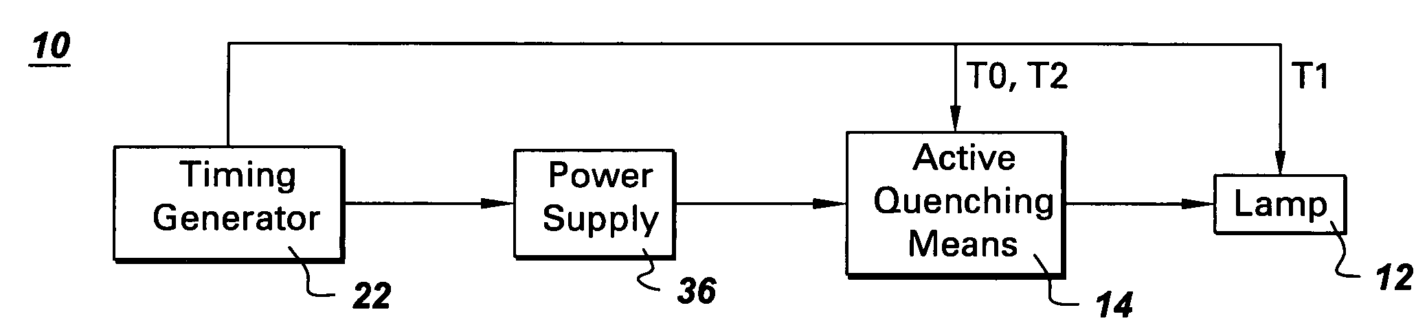
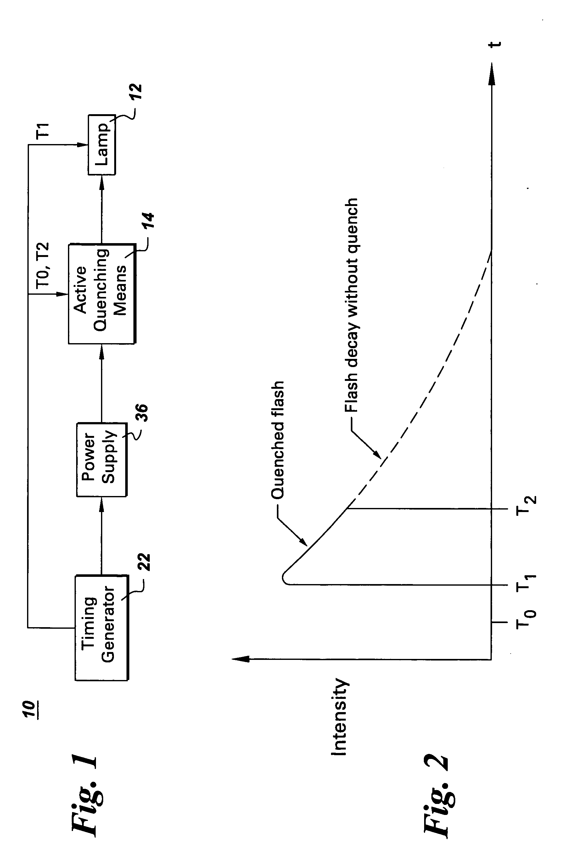
[0021] An actively quenched lamp 10 embodiment of the invention is described first with reference to FIGS. 1 and 2. As shown in FIG. 1, the actively quenched lamp 10 includes a lamp 12, and an active quenching means 14 configured to quench the lamp. Exemplary lamps 12 include quartz lamps and high power flash lamps driven by a power supply 36 and used for transient infrared imaging, such as halogen lamps, flash lamps, and arc lamps. One commercially available high power flash lamp is a Speedotron model 105 flash lamp, which can be driven by a Speedotron 4803, 4.8 Kilojoule (KJ) power supply, both of which are manufactured by Speedotron Corp., Chicago, Ill.

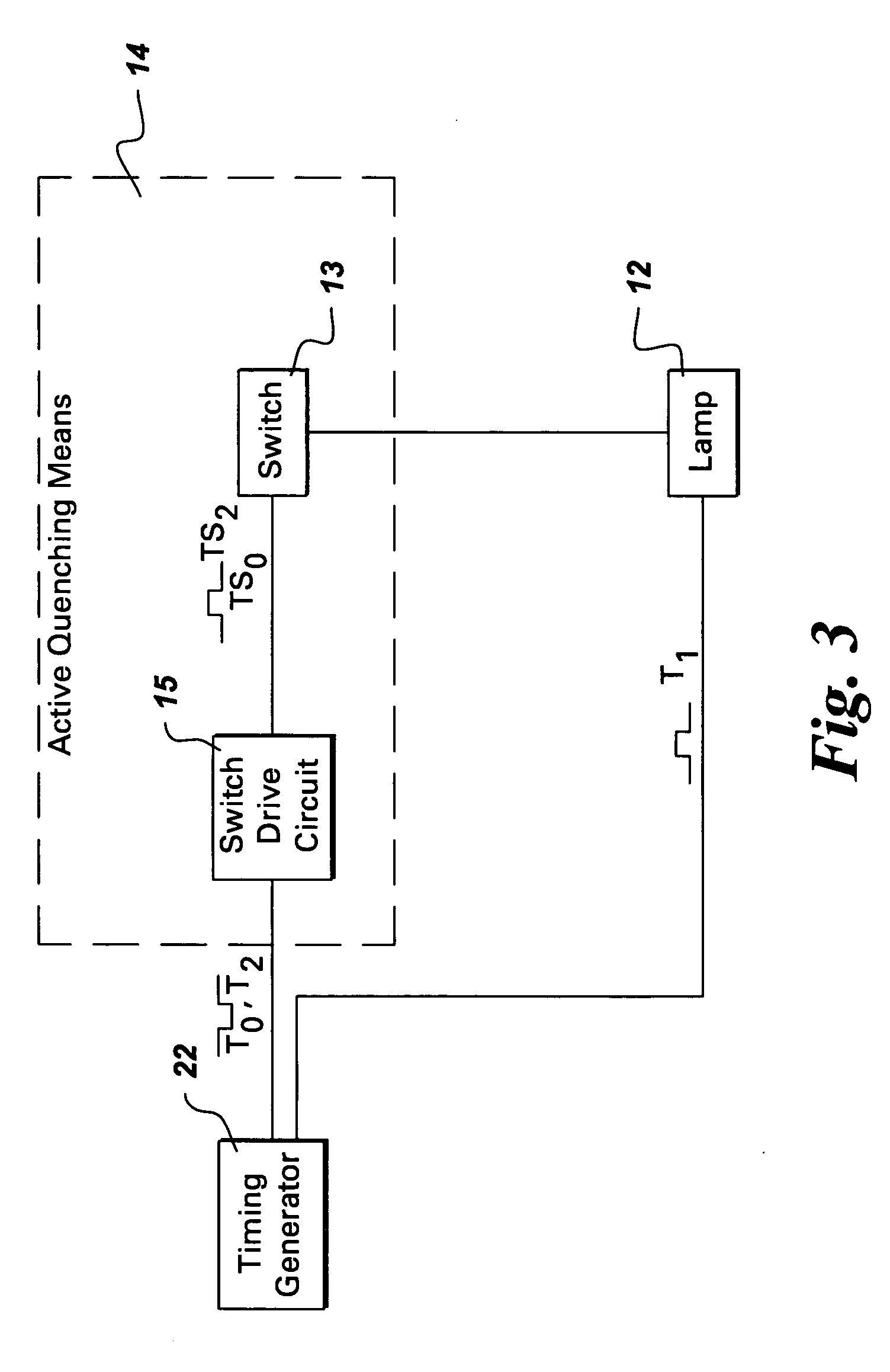
[0022] The active quenching means 12 may be a discrete component of the actively quenched lamp 10, as shown in FIG. 1. Another configuration would be to include the active quenching means 12 within another component, for example, within the power supply 36 driving the lamp 12.

[0023]FIG. 2 is an exemplary timing diagram for the ac...


PUM

PropertyMeasurementUnit
voltageaaaaaaaaaa
switch-drive voltageaaaaaaaaaa
IR thermography imagingaaaaaaaaaa

Abstract

An actively quenched lamp includes a lamp and an active quenching means configured to quench the lamp. An infrared (“IR”) thermography imaging system includes at least one lamp configured to heat a surface of an object to be imaged, at least one active quenching means configured to quench the lamp, and an IR camera configured to capture a number of IR image frames of the object. A method, for actively controlling flash duration for IR thermography, includes generating an initial control signal T0, a lamp control signal T1, and a control signal T2. The method further includes activating a quenching means in response to initial control signal T0, to allow current I to flow to a lamp, activating the lamp in response to lamp trigger signal T1, and turning off the quenching means in response to control signal T2 to cut off the current I to the lamp.

Description

BACKGROUND OF THE INVENTION [0001] The invention relates generally to infrared (“IR”) thermography and, more particularly, to actively controlling the flash duration of an IR lamp for an IR thermography imaging system. [0002] IR transient thermography is a versatile nondestructive testing technique that relies upon temporal measurements of heat transference through an object to provide information concerning the structure and integrity of the object. Because heat flow through an object is substantially unaffected by the micro-structure and the single-crystal orientations of the material of the object, an IR transient thermography analysis is essentially free of the limitations this creates for ultrasonic measurements, which are another type of nondestructive evaluation used to determine wall thickness. In contrast to most ultrasonic techniques, a transient thermographic analysis approach is not significantly hampered by the size, contour or shape of the object being tested and, more...

Claims


Application Information

Patent Timeline
Patent Type & Authority Applications(United States)
IPC IPC(8): G01J5/48G01N25/72
CPCG01N25/72
Inventor RINGERMACHER, HARRY ISRAELZHANG, RICHARD S.FILKINS, ROBERT JOHN
Owner GENERAL ELECTRIC CO
Why Eureka
Try Eureka