
Optical communication system and method using spread-spectrum encoding

Inactive Publication Date: 2005-01-27
AVAGO TECHNOLOGIED FIBER IP SINGAPORE PTE LTD
View PDF10 Cites 50 Cited by
  • Summary
  • Abstract
  • Description
  • Claims
  • Application Information

AI Technical Summary

Benefits of technology

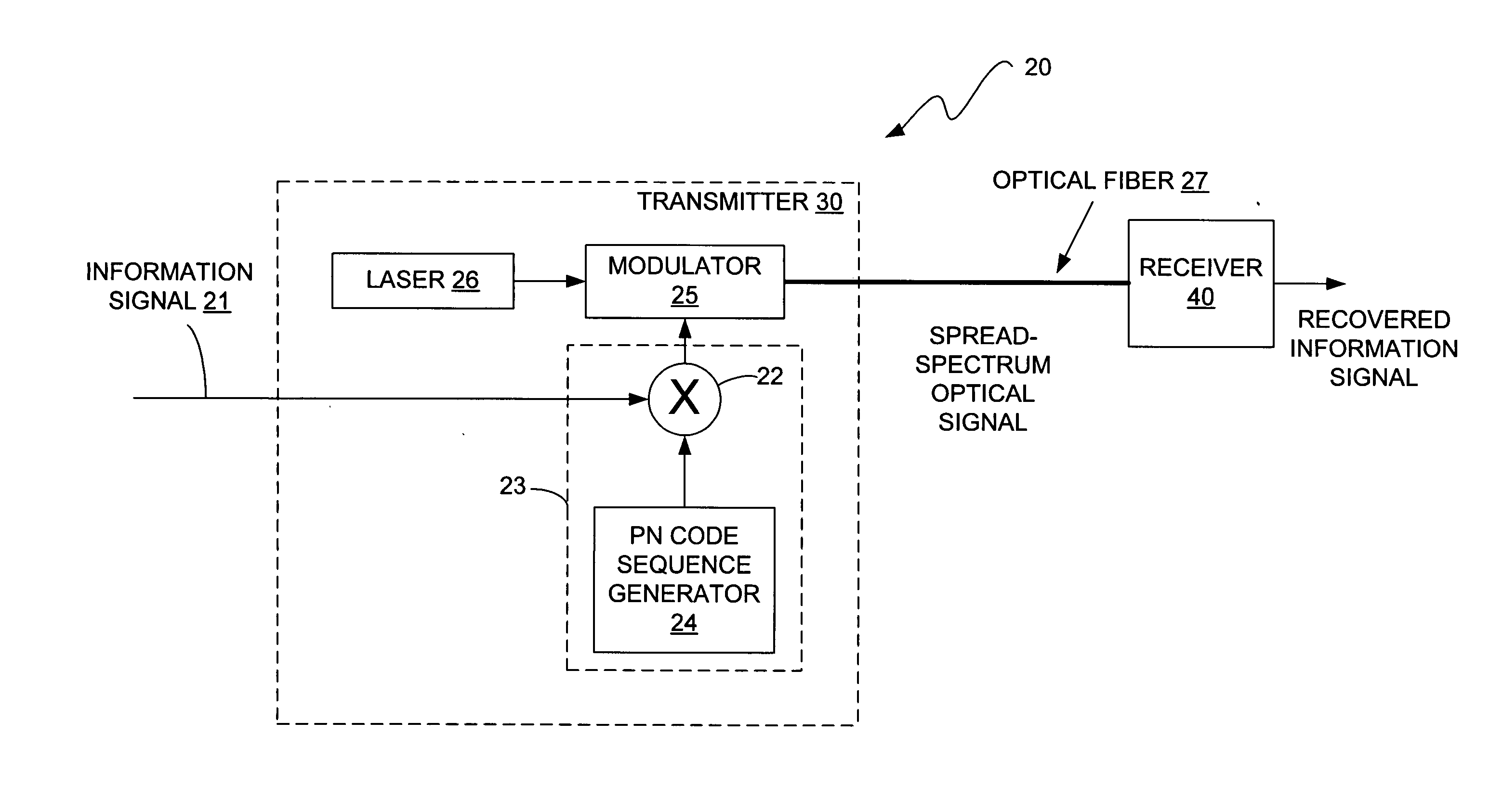
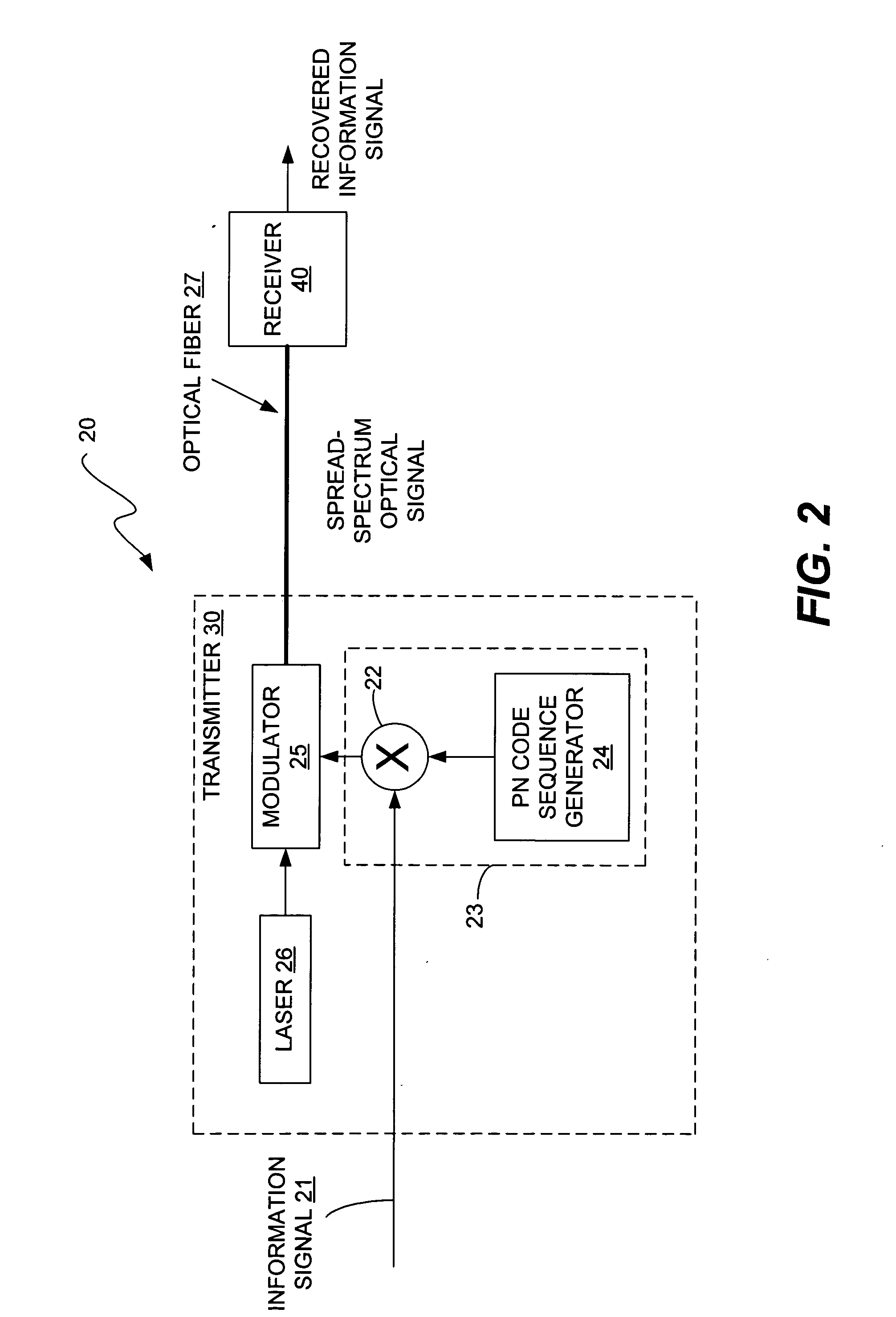
[0010] The information signals to be transmitted through an optical communication system are subject to spread-spectrum encoding prior to transmission and the spread-spectrum optical signal is decoded to recover the information signals at the receiver. Using spread-spectrum encoding to spread the spectrum of information signals enables significantly higher levels of inter-channel interference to be tolerated than in conventional optical communications systems. The higher allowable levels of inter-channel interference allow the bandwidth of the optical channels of the optical communication system to be increased. This in turn allows the bit rate of the channels to be increased significantly.
[0011] Applying spread-spectrum encoding to the information signals increases the bandwidth requirement for each information signal by a factor of L, where L is the ratio of the chip rate of the spread-spectrum information signal to the bit rate of the original information signal. However, significantly more than L spread-spectrum information signals can be transmitted in the same optical channel and can be successfully recovered at the receiver. Accordingly, using spread spectrum encoding provides a significant increase in the capacity of the optical communication system.

Problems solved by technology

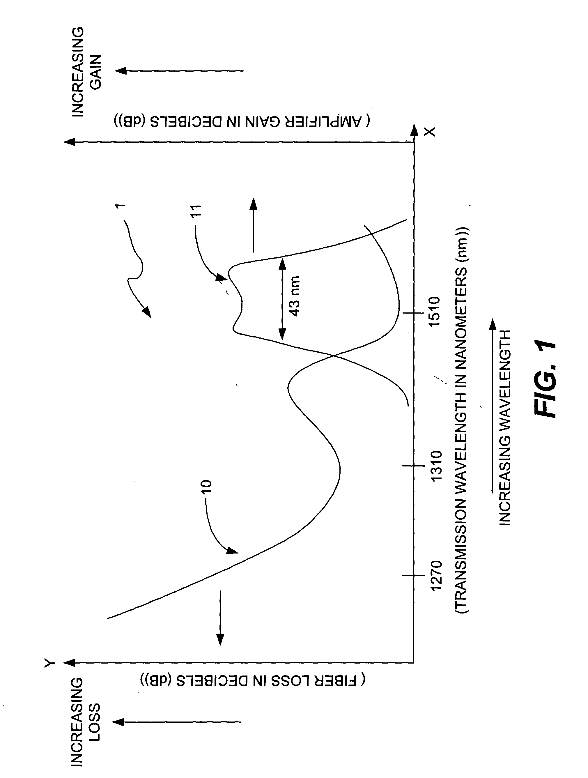
The ability of WDM systems and techniques to increase the capacity of optical communication systems is limited by the constraint on usable transmission wavelengths.
This spacing decreases the number of usable transmission wavelengths, thereby further limiting capacity.
Wider filter bandwidths would produce unacceptable levels of inter-channel interference because of the gradual roll-off of the out-of-band rejection characteristic.
In addition, factors such as temperature drift of both the laser frequency and the center frequency of the filter, aging of the filter components, etc., further reduce the usable bandwidth of the channel.

Method used


Image

  • Optical communication system and method using spread-spectrum encoding
  • Optical communication system and method using spread-spectrum encoding
  • Optical communication system and method using spread-spectrum encoding

Examples


Embodiment Construction

[0030] The invention uses spread-spectrum encoding in conjunction with wavelength division multiplexing (WDM) to increase the capacity of an optical communication system. As stated above, increasing bit rate in a conventional optical WDM communication system, which requires increasing the pass bandwidths of the channel filters, causes increased inter-channel interference. Such increased inter-channel interference is usually not allowable in conventional optical WDM communication systems. For these reasons, conventional optical WDM communication systems are not able to satisfy demand for greater capacity.

[0031] As stated above, the current 80 channel, 10 Gb / s per channel WDM optical communication system has a capacity that is very near the maximum achievable capacity due to practical limitations imposed by parameters such as laser drift and drift of the center frequency of the demultiplexing filters. The invention provides a way to increase the capacity of an optical WDM communicati...


PUM


Abstract

Using spread-spectrum encoding the spread the spectrum of information signals transmitted in an optical communications system enables significantly higher levels of inter-channel interference to be tolerated than in conventional optical communication systems. This allows the bandwidth of the optical channels of the optical communication system to be increased, and the bit rate of the channels to be increased. Applying spread-spectrum encoding to the information signals increases the bit rate of each information signal by a factor of L, but significantly more than L spread-spectrum information signals can be transmitted in the same optical channel and can be successfully recovered at the receiver. Accordingly, using spread spectrum encoding provides a significant increase in the capacity of the optical communication system.

Description

TECHNICAL FIELD OF THE INVENTION [0001] The invention relates to communications and, more particularly, to using spread-spectrum encoding in conjunction with optical wavelength division multiplexing (WDM) to increase the data capacity of an optical communication system. BACKGROUND OF THE INVENTION [0002] Wavelength division multiplexing (WDM) systems are employed in optical communication systems to enable information to be transmitted at multiple wavelengths over a single optical fiber, thereby increasing the amount of information that can be transmitted. The theoretical minimum optical loss for glass fiber is about 0.16 decibels per kilometer (dB / km), and this theoretical minimum occurs at a wavelength of about 1550 nanometers (nm). Erbium-doped amplifiers, which currently are the most common type of amplifier used for amplifying optical signals carried on optical fibers, perform best in the wavelength range of approximately 1520 to 1565 nm. Therefore, these amplifiers have the bes...

Claims


Application Information

Patent Timeline
IPC IPC(8): H04B10/155
CPCH04B10/5053H04B10/58H04B10/541
Inventor TRUTNA, WILLIAM R. JR.
Owner AVAGO TECHNOLOGIED FIBER IP SINGAPORE PTE LTD
Learn More