
Transport platform

a technology for transport platforms and cargo containers, applied in the field of transport platforms, can solve the problems of limiting the utility and the number of platforms, affecting the use of open transport platforms, and unable to dispose of anything other than 40′8′ iso containers in the hold, so as to increase the size and variety of cargo

Inactive Publication Date: 2005-01-27
ITL TECH
View PDF36 Cites 6 Cited by
  • Summary
  • Abstract
  • Description
  • Claims
  • Application Information

AI Technical Summary

Benefits of technology

[0012] The invention is directed to solving the above mentioned problems and to increasing the size and variety of cargo which can be carried on a container ship by open transport platforms, both below deck in the holds of the container ships, as well as on deck.

Problems solved by technology

Open transport platforms, which have been used to transport vehicles or the like, have, due to their configuration and limited structural strength, had to be left to last during the loading process so that they can be placed on top of the uppermost containers on the deck of the container ship.
That is to say, due to the limited ability of the platforms to bear large vertically acting loads such as those generated by the placement of a fully laden container on top thereof, the platforms have had to be disposed at the very tops of the container stacks.
This, of course, severely limits both their utility and the number of platforms which can be carried on any one vessel.
A further drawback that open transport platforms have suffered from results from the fact that the holds of modern container ships are usually constructed to receive predetermined sized containers which are usually 40′×8′ long ISO (International Standards Organization) containers.
However, it has been extremely difficult, if not impossible, to dispose anything but the 40′×8′ ISO containers in the hold and attempts to dispose transport platforms below deck have not met with any success.
Thus, storage in such holds has been limited to the above mentioned 40′×8′ ISO containers which are dimensioned to fit in the cell guides.
This means that off-sized containers or platforms, which are either wider or narrower than the width of the cell guides, cannot be secured below deck in the holds and are relegated to possible disposition above deck.

Method used


Image

  • Transport platform
  • Transport platform
  • Transport platform

Examples


first embodiment

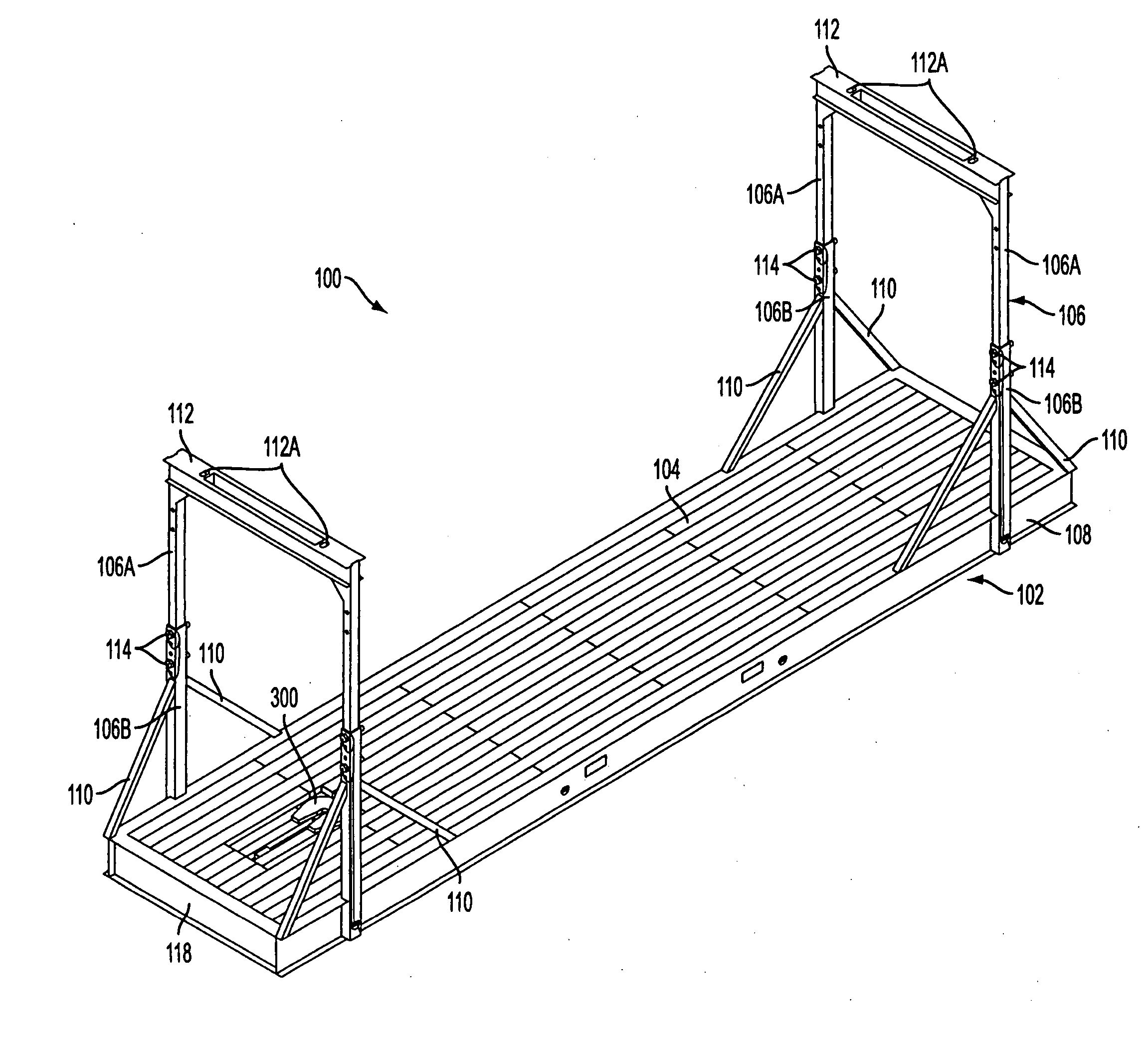
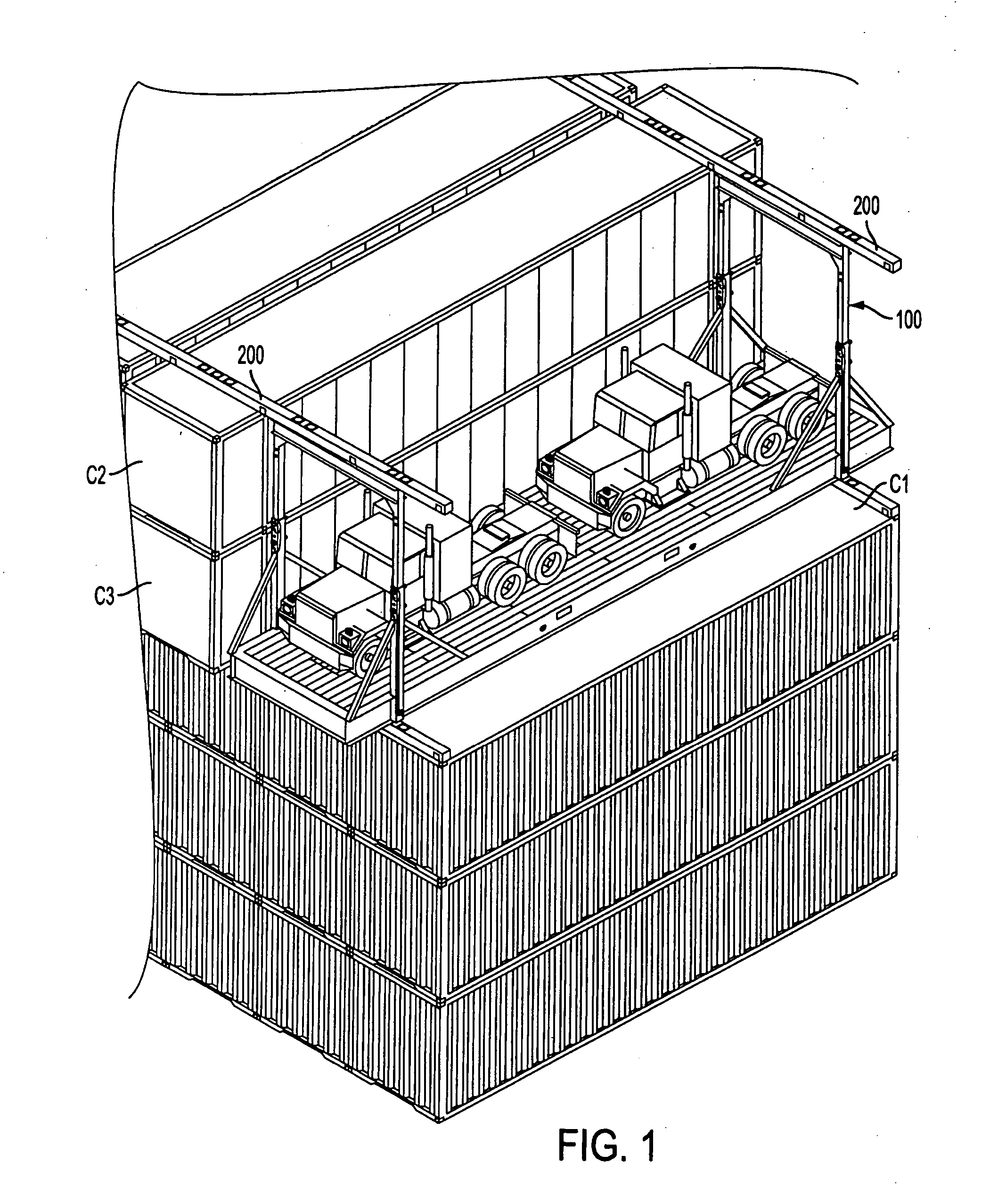
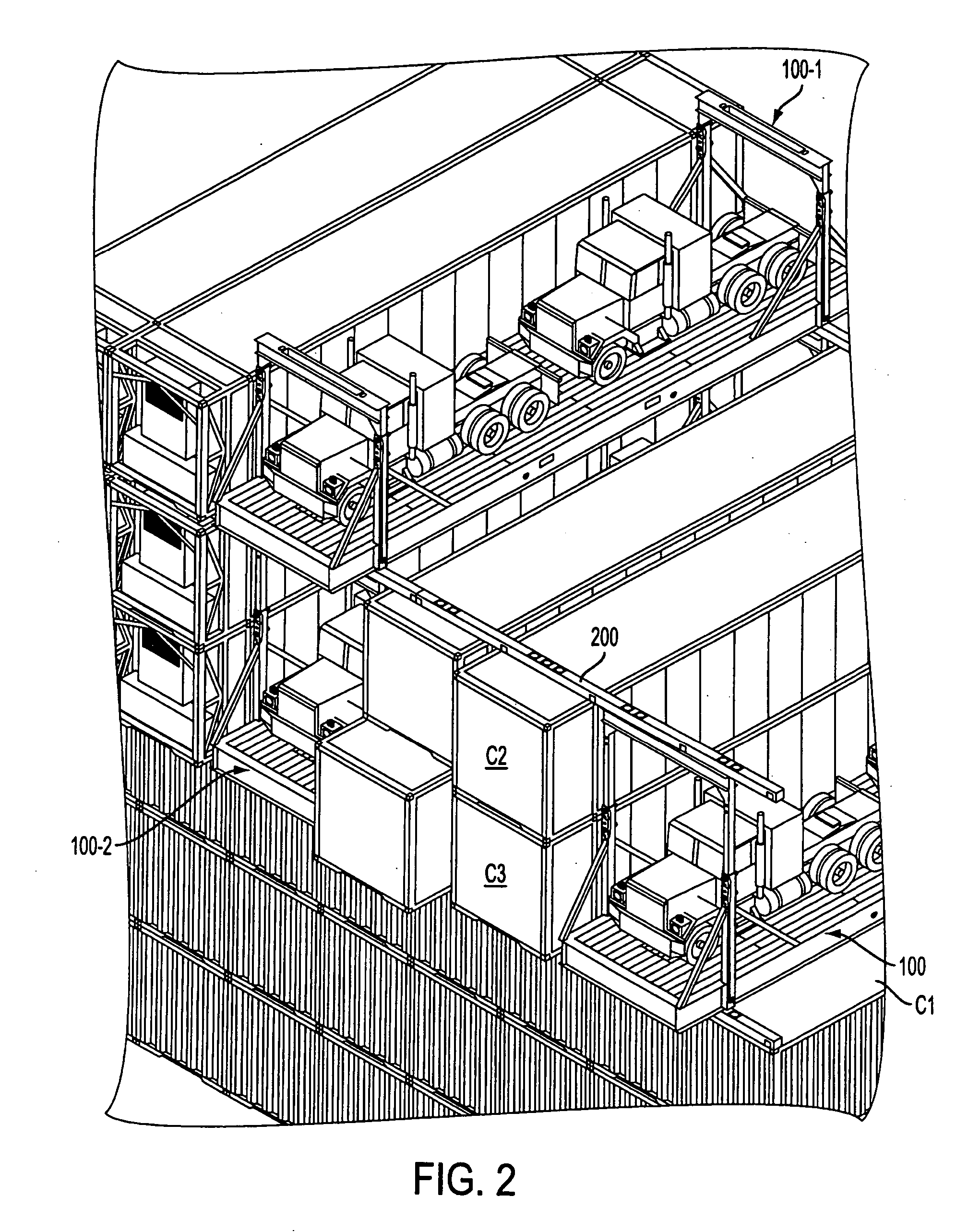
[0069] The upper cross-members 112 are formed with apertures 112A into which twist locks associated with the connection rails or beams 200, can be disposed and engaged with the cross-members when the connection rails 200 are placed in position in the manner illustrated in FIGS. 1 and 2. These connection rails 200 are interconnected to the tops and bottoms of container and platforms through twistlock devices. The interposition of these connection rails 200 between layers in the container enables vertical load to be shared between the containers and the masts of the transport platforms. These rails 200 also laterally interconnect the containers and platforms so as to create a unit of interconnected elements which interlocks the stacks together and prevents lateral movement of any one container with respect to an adjacent container / platform.

[0070] The platforms are constructed in a manner wherein lower cross-members 116 extend across the lower surface of the transport platform 100 at l...

second embodiment

[0075]FIGS. 7-23 show the invention. This embodiment is applicable to below-deck storage in the holds which have thus far been limited to the 40′×8′ ISO containers for reasons address above. These holds are formed along the almost the whole length of the container ship in order to maximize the cargo carrying capacity of the same. The width of the holds in the parallel mid-body of the ships remains constant. However, in the bow and aft sections of the vessel, the tapering configuration of the ships hull demands that the widths of the holds reduce as they approach the ends of the vessel.

[0076]FIG. 7 is a perspective view showing, merely by way of example, a stack of 40′ ISO containers C4; four stacks of transport platforms 400 (400-1 . . . 400-4) according to the second embodiment of the invention; and a further stack of ISO containers C5, which are disposed in a hold HLO in the illustrated manner. The bulkhead B / H is shown as having a plurality of vertically extending T-guide members...

third embodiment

[0097] The hinges 665 in this third embodiment are constructed so that the pivot shaft is a bolt which can be removed to allow the mast be disconnected / replaced or the like.

[0098] As shown in FIG. 19, further outwardly extending projections 667 are provided on the masts. These projections 667 are slotted and are arranged so that the slots align with one of the slots in the end member. Alternatively, this projection can take the form of a cross-member which interconnects the lower ends of the masts and thus adds rigidity to the structure. This member, if provided, is formed with a plurality of slots which correspond to and are aligned with those formed in the end of the platform.

[0099] FIGS. 27 to 29 show an embodiment of the above mentioned connection rail arrangement. The embodiment of the connection rails 500 shown in FIGS. 27-29 are such as to have a hollow cross-section as seen from the end view shown in FIG. 29 and are provided with detachable skirts 510 which are bolted in po...


PUM


Abstract

An embodiment of a transport platform has a platform having first and second end members in which spaced vertically extending first slots are formed, the first slots being adapted to receive one of a plurality of vertically extending guide members that are provided on bulkheads of a container ship hold. The transport platform also has first and second sets of vertically extending pillars which are respectively provided at first and second ends of the platform. First and second cross members respectively interconnect the upper ends of the first and second set of pillars. The first and second cross members each having spaced vertically extending second slots that are aligned with the vertically extending first slots and which are adapted to receive the vertically extending guide members which are formed on the bulkheads of the container ship hold.

Description

CROSS REFERENCE TO RELATED APPLICATIONS [0001] The present application is a continuation-in-part of a U.S. patent application Ser. No. 10 / 622,536 filed on Jul. 21, 2003 in the name of Bernard S. Sain, the entire contents of which are hereby incorporated by reference.BACKGROUND OF THE INVENTION [0002] 1. Field of the Invention [0003] The present invention relates generally to transport platforms for transporting cargo on container ships, and more specifically to open transport platforms for transporting large vehicles / equipment and the like type of cargo and which are adapted for stacking both above and below the decks of container ships. [0004] 2. Description of the Related Art [0005] Open transport platforms, which have been used to transport vehicles or the like, have, due to their configuration and limited structural strength, had to be left to last during the loading process so that they can be placed on top of the uppermost containers on the deck of the container ship. That is ...

Claims


Application Information

Patent Timeline
Patent Type & Authority Applications(United States)
IPC IPC(8): B60P7/06B63B25/00B65D88/00B65D88/12
CPCB63B25/004B63B25/008B65D2585/6872B65D88/129B65D2585/686B65D88/005
Inventor SAIN, BERNARD S.
Owner ITL TECH
Learn More