Blind rivet with extended adhesive reservoir

a technology of adhesive reservoir and rivet, which is applied in the direction of threaded fasteners, screw heads, manufacturing tools, etc., can solve the problems of limited amount of adhesive that could be effectively extruded, blind side is not accessible, and limited amount of rivet head that could be formed, so as to strengthen the bond between the rivets

Inactive Publication Date: 2005-01-27
GM GLOBAL TECH OPERATIONS LLC
View PDF9 Cites 6 Cited by
  • Summary
  • Abstract
  • Description
  • Claims
  • Application Information

AI Technical Summary

Benefits of technology

[0011] In order to obtain a controlled collapse of the second portion of tubular body, weakened regions are formed in that portion of the body to better obtain uniform or symmetrical folding of the tube material in shaping the blind side rivet head. Corrugations or other forms of weakened bands are formed along the length of the second portion so that the metal folds neatly to constitute the second rivet head under the axial force of the mandrel head on the end of the tubular bo

Problems solved by technology

The shank can be inserted through the assembly so that the rivet head engages the accessible side, but the blind side is not accessible for upsetting the protruding shank from that side to form the opp

Method used


Image

  • Blind rivet with extended adhesive reservoir
  • Blind rivet with extended adhesive reservoir

Examples


first embodiment

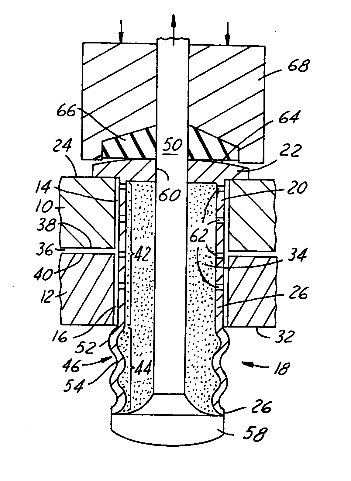
[0018] the adhesive encapsulated blind rivet design of the present invention is shown in the enlarged sectional view of FIG. 1. Broken away portions of two sheet metal parts 10, 12 are assembled for placement of a rivet assembly 18. A rivet hole 14 has been formed in part 10 and a similar rivet hole 16 has been formed in part 12. Holes 14, 16 are then aligned for insertion of blind rivet 18. Although parts 10, 12 are held together for riveting, there remains a small gap 36, which is exaggerated in size in enlarged view FIG. 1, formed between faying surfaces 38, 40 of parts 10, 12, respectively. As further discussed in this specification, gap 36 provides a space for a film of adhesive to enter upon being extruded from rivet 18.

[0019] Blind rivet assembly 18 has a rivet head 22 and a tubular rivet body 20 that is inserted in aligned holes 14, 16. For purposes of illustration, part 10 and its upper surface 24 represents the accessible side of the assembly and rivet head 22 fits against...

third embodiment

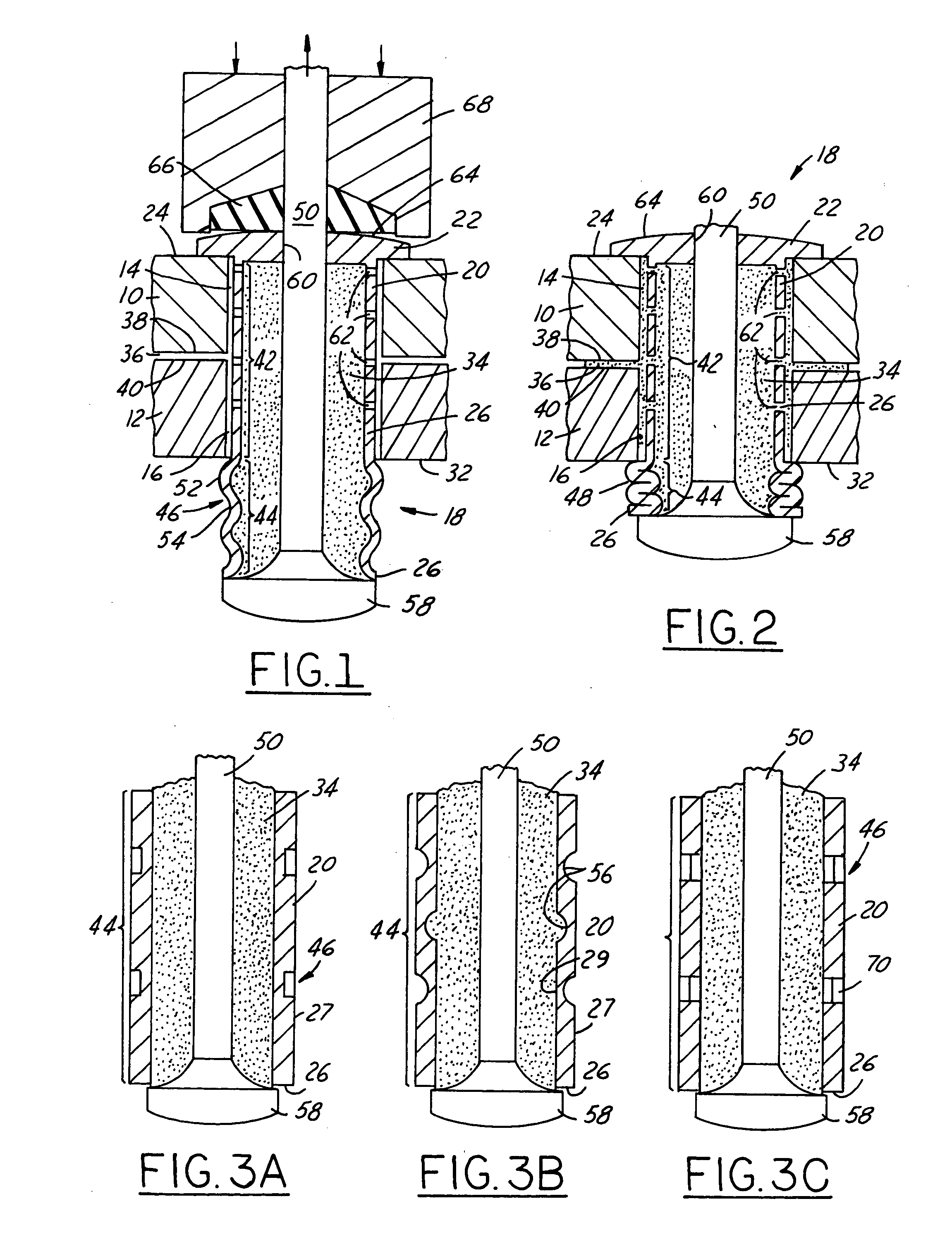
[0030]FIG. 3C illustrates weakened bands in extended body portion 44. Axially spaced, circumferential bands of metallurgically softened or weakened metal 70 are formed by a suitable heat treatment or like softening process. These softened or weakened bands 70 are made for example, by laser heat treating, or the like. The softened regions may be formed as continuous circumferential bands or as a linear band of individual soft spots selected in a pre-determined manner. The weakened metal 70 can extend through the thickness of the second body portion 44 to provide metal folding lines that accommodate a symmetrical folded collapse of the tubular body during setting of the rivet assembly 18. In other words, softening of the rivet body completely through its thickness permits the material to fold in a natural progression as the mandrel head 58 is pulled against the end 26 of the rivet body 20.

[0031] When the adhesive is extruded from reservoir 34 during installation of rivet 18, adhesive ...


PUM


Abstract

This invention provides a design of an adhesive encapsulated blind rivet for joining an assembly of overlying parts having an accessible side and an inaccessible side. The rivet comprises a rivet head and tubular rivet body. A mandrel is inserted through the open end of the tubular rivet body and through a mandrel hole in the rivet head. A mandrel head engages the end of the tubular body. The tubular body is filled with a mass of latent adhesive around the mandrel. The rivet body is longer than the thickness of the parts to be joined to accommodate a substantial amount of adhesive for expulsion through holes in the rivet body located within the thickness of the assembled parts. The portion of the rivet body extending beyond the blind side of the assembled parts is weakened in a pattern of corrugations or other bands for folding of the end of the tubular body in setting the blind side of the rivet and expelling the larger quantity of adhesive against and between the riveted parts.

Description

TECHNICAL FIELD [0001] This invention relates generally to blind rivets. More specifically, this invention relates to a rivet having an extended adhesive reservoir and to a method of using the adhesive filled rivet to join a plurality of parts. BACKGROUND OF THE INVENTION [0002] The common rivet has a head and a shank. The shank is inserted through aligned holes from one side of assembled metal sheets or plates or other parts. The rivet head engages one side of the assembly and the shank extends through the other side. The extended end of the shank is struck and upset or otherwise deformed to form a second head engaging the other side of the assembly and thus secure the parts at the rivet site. In a blind rivet situation only one side of the assembly is available for the riveting operation. The shank can be inserted through the assembly so that the rivet head engages the accessible side, but the blind side is not accessible for upsetting the protruding shank from that side to form t...

Claims


Application Information

Patent Timeline
IPC IPC(8): F16B11/00F16B19/10
CPCF16B11/006Y10S411/93F16B19/1081
Inventor STEVENSON, ROBINWANG, PEI-CHUNG
Owner GM GLOBAL TECH OPERATIONS LLC
Why Eureka
Try Eureka