Fuel cell stack

a fuel cell and stack technology, applied in the field can solve the problems of fuel cell stacks not being mounted in vehicles suitably, metal separators are likely to be deformed undesirably, power generation performance and sealing characteristics may be lowered undesirably,

Active Publication Date: 2005-01-27
HONDA MOTOR CO LTD
View PDF9 Cites 26 Cited by
  • Summary
  • Abstract
  • Description
  • Claims
  • Application Information

AI Technical Summary

Benefits of technology

[0013] A main object of the present invention is to provide a fuel cell stack using metal separators to achieve a compact size and a lightweight in which the desired power generation performance and sealing characteristics are maintained in each of unit cells.
[0019] According to the present invention, the stack body is housed in the box-shaped casing. Therefore, although the separators are thin corrugated plates, and do not have any shape retaining characteristics, the pressure is uniformly applied to surfaces of the unit cells. Thus, power generation performance and sealing characteristics are improved in each of the unit cells. Since the coupling pins are used for coupling the end plates and the side plates, operations such as tightening adjustment of bolts are not required at the time of assembling the fuel cell stack. Thus, the fuel cell stack can be assembled simply. Further, since the coupling pins are used in the casing, the sides of the stack body are kept in parallel, and are not likely to be displaced undesirably. The positional displacement due to vibrations or shocks can be prevented.
[0020] Further, since the elasticity of the metal separators is advantageously utilized, it is not required to provide any belleville spring in the casing. Thus, a compact and light fuel cell stack as a whole can be produced easily. Since no belleville spring is used, the stack body including the metal separators is not deformed undesirably.
[0021] The stack body is not deformed or twisted undesirably. Therefore, dimensional variation in the fuel cell stack is reduced. In practical use, the fuel cell stack is suitably mounted in a vehicle. Further, since the side plates are securely coupled together by the angle members, even if an external force is applied to the fuel cell stack, lateral positional displacement is not likely to occur in each of the unit cells. Even if shocks are applied to the unit cells, the power generation performance and the sealing characteristics can be maintained.
[0022] The insulating spacer member is interposed between the terminal plate and the end plate. Therefore, even if there is dimensional variation of the stack body due to the difference of dimensions depending on the unit cells, the dimensional variation is absorbed simply by changing the thickness of the spacer member. The fuel cell stack has a small size and lightweight as a whole. The fuel cell stack can be assembled easily and simply.
[0023] The sides of the rectangular end plates are coupled to the side plates by the coupling pins, respectively. Thus, the stack body is not tilted undesirably unlike the case where only two sides of the plates are coupled. The unit cells are stacked in the horizontal direction. Therefore, the sides of the stack body can be arranged easily in parallel unlike the case where the unit cells are stacked in the vertical direction. Accordingly, the undesirable deformation of the stack body can be reduced.

Problems solved by technology

In particular, when a thin corrugated metal plate is used as the separator, the metal separator is likely to be deformed undesirably due to the tightening force applied to the metal separator.
In practical use, the fuel cell stack is not suitably mounted in a vehicle.
Thus, the power generation performance and sealing characteristics may be lowered undesirably.
In particular, the tightening bands 5 are not suitable for securely tightening the stack body 2.
When vibrations or shocks are applied to the stack body 2, positional displacement may occur undesirably in the stack body 2.

Method used


Image

  • Fuel cell stack
  • Fuel cell stack
  • Fuel cell stack

Examples


Embodiment Construction

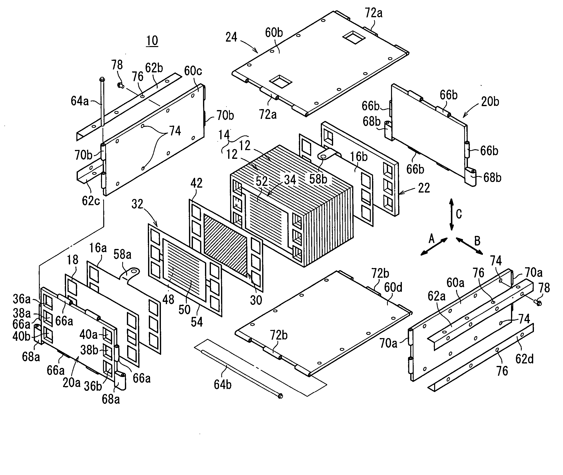
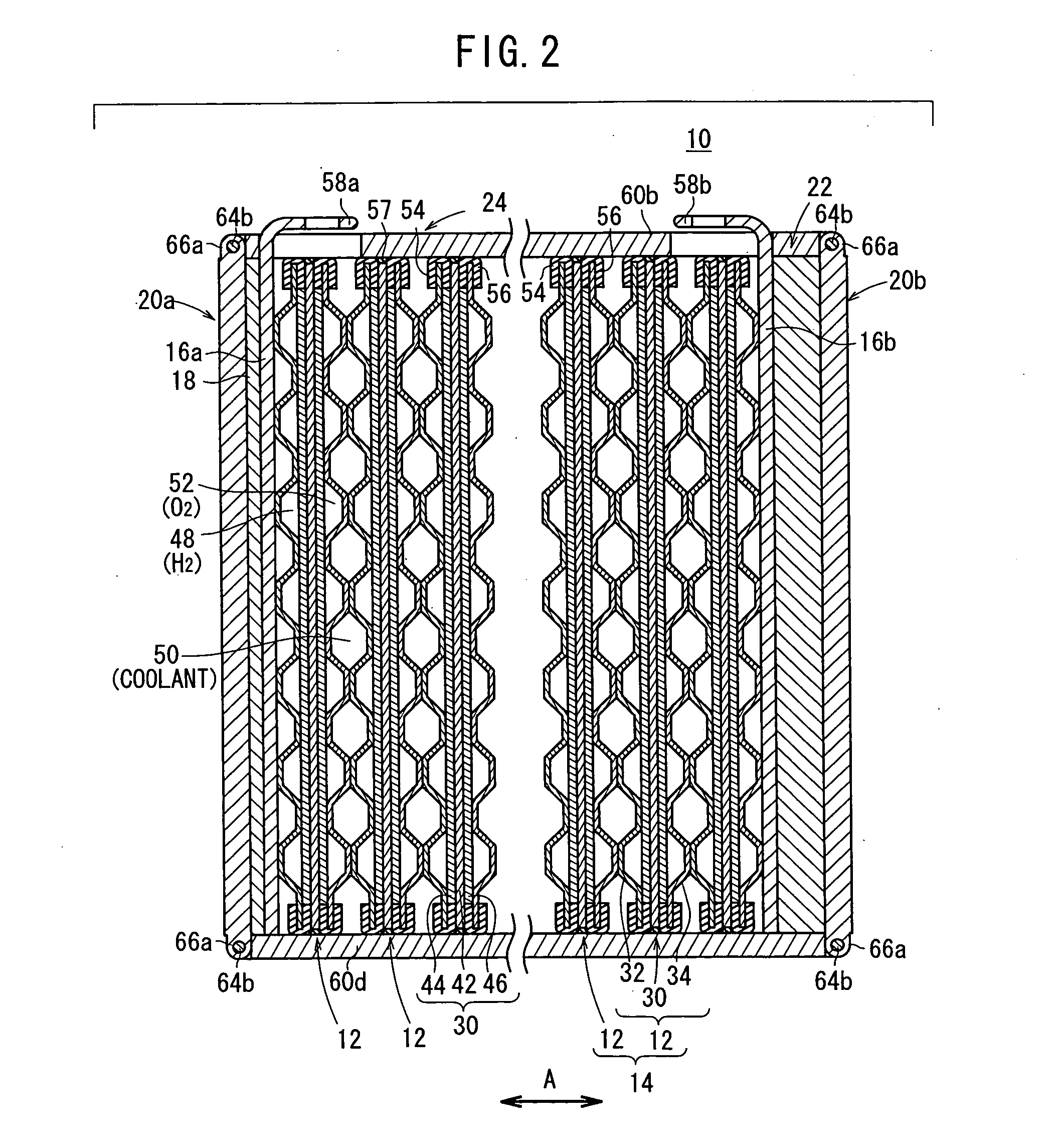
[0030]FIG. 1 is an exploded perspective view schematically showing part of a fuel cell stack 10 according to an embodiment of the present invention. FIG. 2 is a cross sectional side view showing part of the fuel cell stack 10.

[0031] As shown in FIG. 1, the fuel cell stack 10 includes a stack body 14 formed by stacking a plurality of unit cells 12 horizontally in a stacking direction indicated by an arrow A. At an end of the stack body 14 in the stacking direction indicated by the arrow A, a terminal plates 16a is provided. An insulating plate 18 is provided outside the terminal plate 16a. Further, an end plate 20a is provided outside the insulating plate 18. At the other end of the stack body 14 in the stacking direction, a terminal plate 16b is provided. An insulating spacer member 22 is provided outside the terminal plate 16b. Further, an end plate 20b is provided outside the insulating spacer member 22. Each of the end plates 20a, 20b has a rectangular shape. The fuel cell stack...


PUM


Abstract

A fuel cell stack includes a box-shaped casing and a stack body in the box-shaped casing. The stack body is formed by stacking a plurality of unit cells. The casing includes end plates, a plurality of side plates, angle members, and coupling pins. The angle members couple adjacent ends of the side plates. The coupling pins couple the end plates and the side plates.

Description

BACKGROUND OF THE INVENTION [0001] 1. Field of the Invention [0002] The present invention relates to a fuel cell stack including a box-shaped casing and a stack body in the casing. The stack body is formed by stacking a plurality of unit cells. Each of the unit cells includes an electrolyte electrode assembly and metal separators sandwiching the electrolyte electrode assembly. The electrolyte electrode assembly includes a pair of electrodes, and an electrolyte interposed between the electrodes. [0003] 2. Description of the Related Art: [0004] For example, a solid polymer fuel cell employs a membrane electrode assembly (electrolyte electrode assembly) which includes an anode and a cathode, and an electrolyte membrane (electrolyte) interposed between the anode and the cathode. The electrolyte membrane is a polymer ion exchange membrane. Each of the anode and the cathode is made of electrode catalyst layer of noble metal formed on a base material chiefly containing carbon. The membrane...

Claims


Application Information

Patent Timeline
IPC IPC(8): H01M2/02H01M8/04H01M8/24
CPCH01M8/0258H01M8/04089Y02E60/50H01M8/2475H01M8/248H01M8/241H01M8/0267H01M8/2457H01M8/2483
Inventor SUGITA, NARUTOSHIKOSAKA, TAKASHIISHIZUKA, AYUMUTAKAHASHI, KENMORIKAWA, HIROSHIOHTANI, TERUYUKI
Owner HONDA MOTOR CO LTD
Why Eureka
Try Eureka