Endoscope

a technology of endoscope and target region, which is applied in the field of endoscope, can solve the problems of difficult to accurately lead the distal end of the endoscope to a target region for a short period of time, and misidentification may become a serious obstacle to the navigation of the bronchoscop

Active Publication Date: 2005-01-27
OLYMPUS CORP
View PDF10 Cites 89 Cited by
  • Summary
  • Abstract
  • Description
  • Claims
  • Application Information

AI Technical Summary

Benefits of technology

[0008] An endoscope device in accordance with the present invention comprises: three-dimensional image constructing means for constructing a three-dimensional image of an intracorporeal lumen of a subject on the basis of images representing a three-dimensional field of the subject; an endoscope that picks up images of the intracorporeal lumen of the subject; and navigation image constructing means that constructs a navigation image which includes the endoscopic image of the intracorporeal lumen of the subject that is produced by the endoscope and the three-dimensional image. While pre

Problems solved by technology

As far as an intracorporeal lumen that branches out in multiple stages is concerned, when the position of an abnormality is close to the terminal of a branch, it is hard to lead the dis

Method used


Image

  • Endoscope
  • Endoscope
  • Endoscope

Examples


Embodiment Construction

[0040] Referring to the drawings, an embodiment of the present invention will be described below.

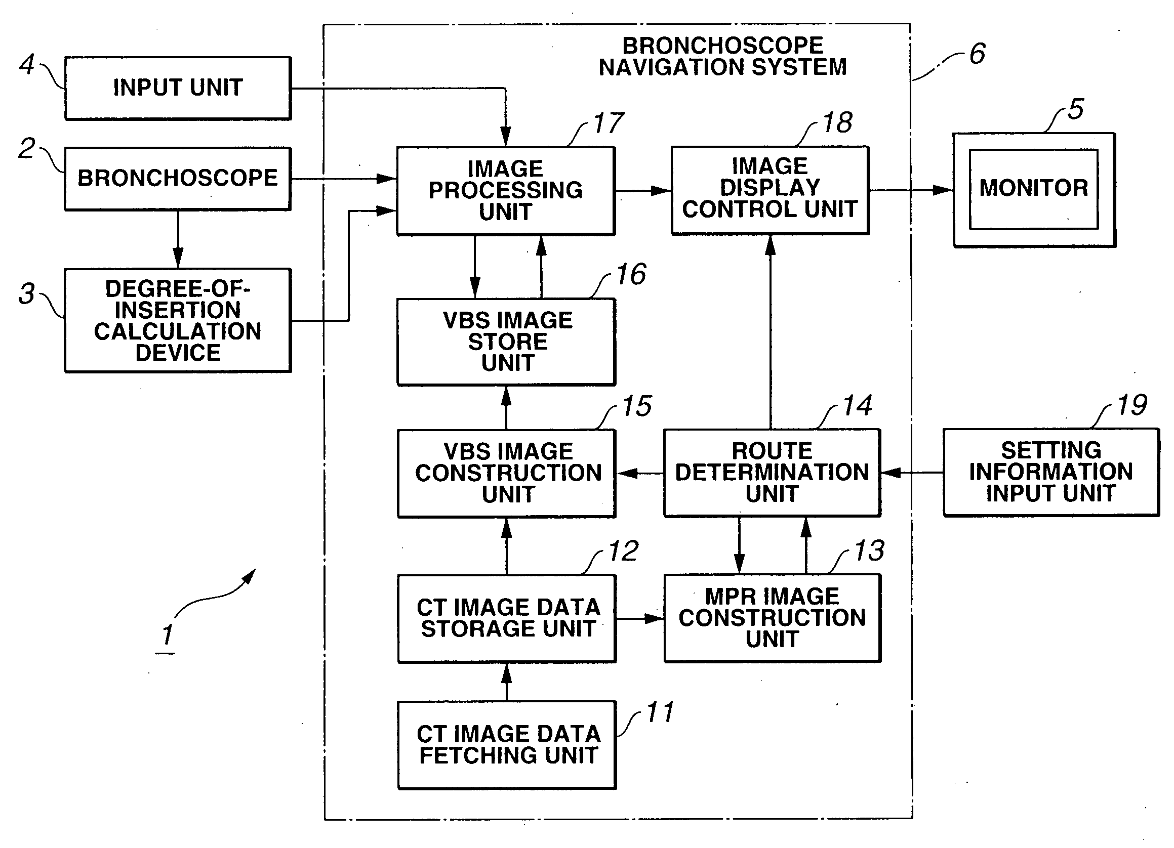
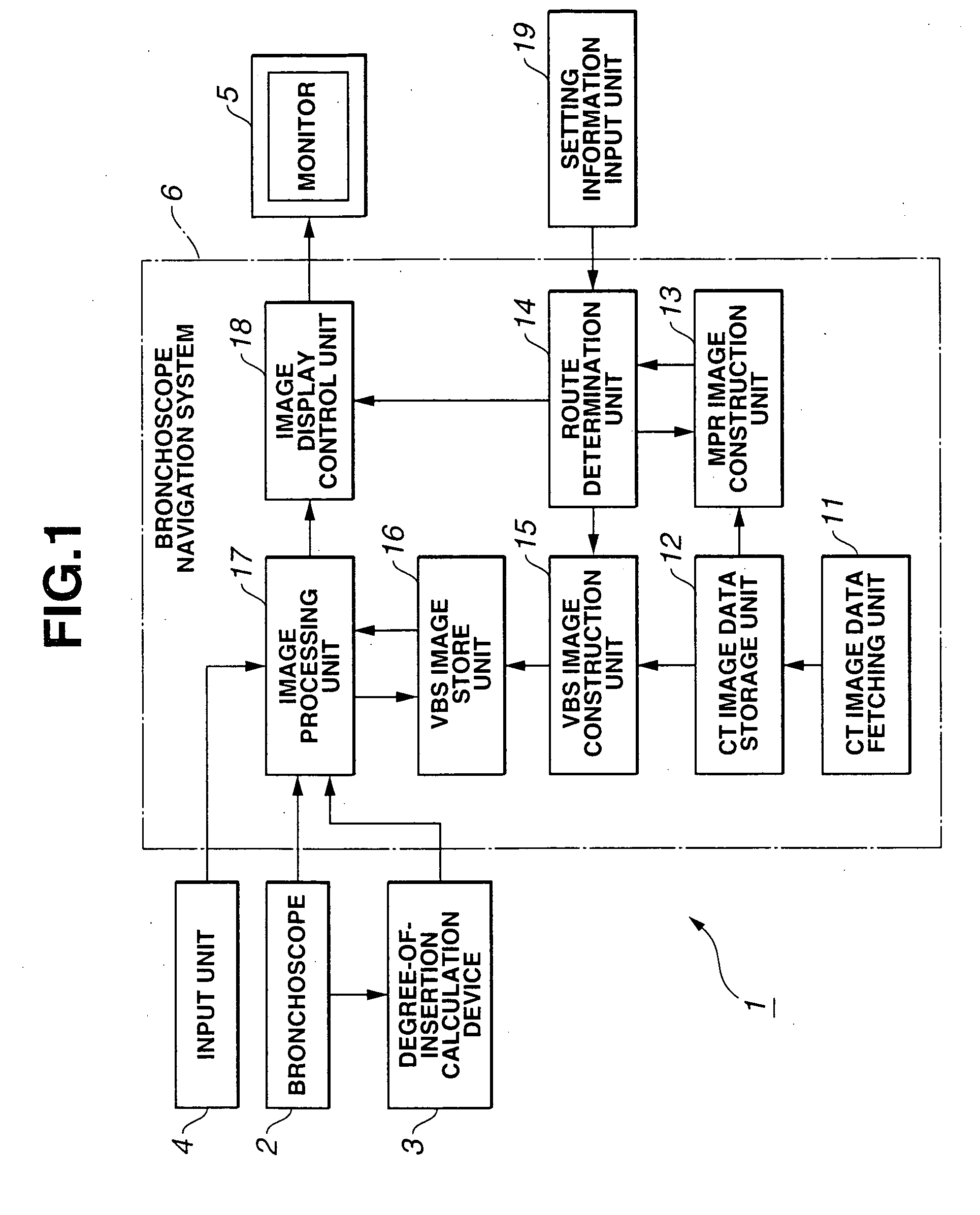
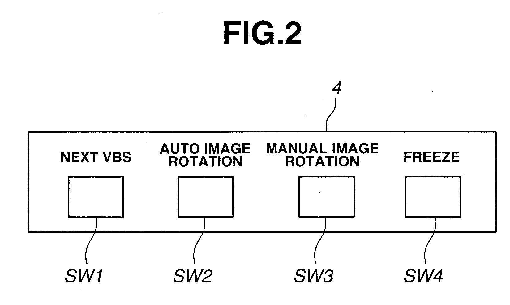
[0041]FIG. 1 to FIG. 30 are concerned with an embodiment of the present invention. FIG. 1 shows the configuration of an endoscope device. FIG. 2 shows the configuration of an input unit shown in FIG. 1. FIG. 3 is a flowchart describing the flow of constructing navigation data to be performed by a bronchoscope navigation device shown in FIG. 1. FIG. 4 is a first diagram showing a route determination screen in which the execution of the process described in FIG. 3 is performed. FIG. 5 is a second diagram showing the route determination screen in which the execution of the process described in FIG. 3 is performed. FIG. 6 is a flowchart describing the flow of route determination to be executed at a step in the process described in FIG. 3. FIG. 7 is a first diagram showing a route determination screen in which the execution of the process described in FIG. 6 is performed. FIG. 8 is a second ...


PUM


Abstract

In an endoscope device 1 in accordance with the present invention, a navigation screen 51 is displayed. The navigation screen 51 includes: an endoscopic live image display area 52 in which a live image produced by a bronchoscope 2 is displayed; a VBS image display area 53 in which a VBS image is displayed; and a thumbnail VBS image area 54 in which images constructed by reducing VBS images that represent all branch points on a route are displayed as thumbnail VBS images representing branch points. Consequently, an endoscope can be reliably navigated to reach a target region using guide images that represent actual branch positions.

Description

TECHNICAL FIELD [0001] The present invention relates to an endoscope device, or more particularly, an endoscope device capable of navigating an endoscope to help insert the endoscope into an intracorporeal lumen, for example, the bronchi. BACKGROUND ART [0002] In recent years, diagnosis based on images has been widely adopted. For example, an X-ray computed tomography (CT) device is used to produce tomographic images of a subject so as to construct three-dimensional image data representing the interior of the subject. The three-dimensional image data is used to diagnose a lesion. [0003] As far as the CT system is concerned, while an X-ray irradiation and detection unit is continuously rotated, a subject is continuously moved in the direction of the body axis. Thus, helical scanning is performed on the three-dimensional field of the subject, and a three-dimensional image is produced based on tomographic images that represent successive sections of the subject in the three-dimensional...

Claims


Application Information

Patent Timeline
IPC IPC(8): A61B1/04A61B1/267
CPCA61B1/00009A61B1/0005A61B1/2676A61B1/042A61B1/00147
Inventor OHNISHI, JUNICHIAKIMOTO, SHUNYAKOBAYASHI, EIICHI
Owner OLYMPUS CORP
Why Eureka
Try Eureka