
Electrode for biomedical measurements

a biomedical and electrode technology, applied in the field of electrodes for biomedical measurements, can solve the problems of large measuring errors, oedema formation in the artificial respiration of the diseased lung, and the need to rule out relatively large measuring errors,

Inactive Publication Date: 2005-01-27
TIMPEL MEDICAL BV
View PDF10 Cites 68 Cited by
  • Summary
  • Abstract
  • Description
  • Claims
  • Application Information

AI Technical Summary

Benefits of technology

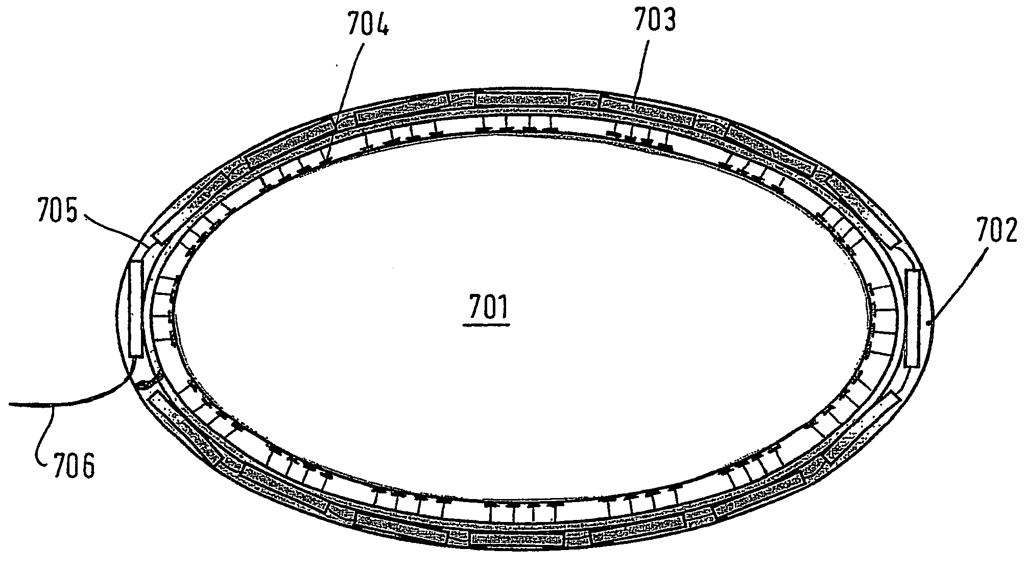
[0009] The object of the invention is to provide an electrode for biomedical measurements and in particular for measurements with electrical impedance tomography which allows measurements which are as free of interference as possible with economical production.
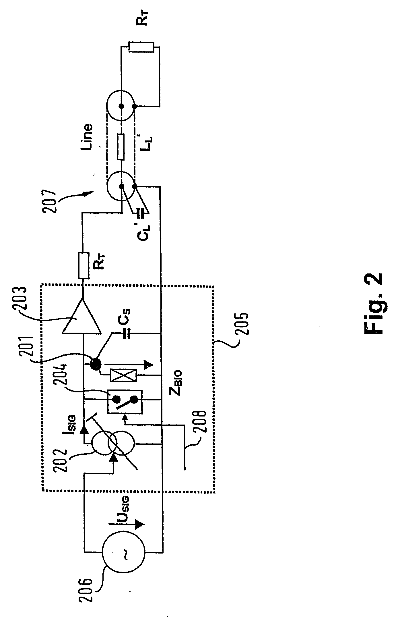
[0011] The essential recognition of the invention consists in that the combination of a line driver and a current source as integrated electronics on or in the vicinity of the contact plate already allows a substantial increase in accuracy compared to known electrodes with continuing low production costs. The production of an integrated electrode as a disposable part is therefore possible with feasible costs.
[0014] According to a further preferred embodiment, a circuit is provided for active compensation of the stray capacitance between the contact plate and reference point. In this manner, line length between the contact plate and the current source and the line driver can be permitted within certain limits, it being possible to eliminate stray capacitances being produced by means of the compensation circuit.

Problems solved by technology

The artificial respiration of the diseased lung in which oedemas have formed is a particular problem as it cannot be precisely monitored whether the lung is already closed or collapsed in certain parts.
However, in this vital application, relatively large measuring errors have to be ruled out as far as possible.
The respective electrodes, however, continue to be connected via feed lines which lead from the electrodes to an evaluation apparatus set up next to the patient, so measuring errors continue to occur owing to impedance changes at the feed lines.
This is primarily because the electrodes have to be used as disposable articles for reasons of hygiene and therefore an expensive wiring of the electrode is out of the question for reasons of cost.

Method used


Image

  • Electrode for biomedical measurements
  • Electrode for biomedical measurements
  • Electrode for biomedical measurements

Examples


Embodiment Construction

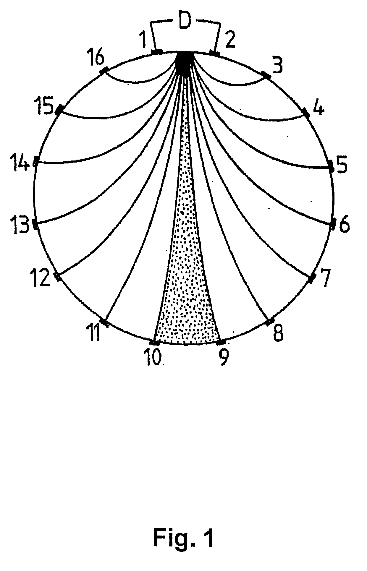
[0034]FIG. 1 shows a section through a thorax with an electrode configuration according to the prior art (U.S. Pat. No. 5,626,146). 16 electrodes are arranged around the thorax with virtually equal spacing. A current is applied between the electrodes 1 and 2. The curved lines are then lines of the same potential with reference to the electrodes 1 and 2 acting as a dipole. The voltage potentials measured at the electrodes 3 to 16 can be traced back along these lines in order to establish the resistance value at points on these lines. Once the respective measurements have been carried out for all possible dipoles, the impedance values determined from each measurement can be accordingly superimposed. This tracing method was selected as an example here and is obviously only one alongside many possible methods of image reconstruction according to the principle of electrical impedance tomography.

[0035]FIG. 2 shows a schematic diagram of an electrode according to the invention. According ...


PUM


Abstract

The invention relates to an electrode for biomedical measurements, in particular for measurements for electrical impedance tomography, which permits measurements with as little interference as possible. The electrodes comprise a contact plate, a line driver with a high-impedance signal input and low-impedance line output and a current source, with a current output and a reference point, whereby the contact plate is connected to the high-impedance signal input of the line driver and to the current output of the current source and the line driver and the current source are arranged in the vicinity of the contact plate.

Description

RELATED APPLICATIONS [0001] This is a continuation of PCT / EP02 / 13026, filed Nov. 20, 2002, hereby incorporated by reference, which claims the priority benefit of German Application No. 101 56 833.9, filed Nov. 20, 2001, hereby incorporated by reference. FIELD OF THE INVENTION [0002] The invention relates to an electrode for biomedical measurements, in particular for measurements for electrical impedance tomography. BACKGROUND OF THE INVENTION [0003] In electrical impedance tomography for regional measurement of pressure-volume ratios, a number of electrodes are placed around the thorax, an alternating current, for example, in the range of 1 kHz to 1 MHz at an amplitude in the range of 1 μA to 10 mA being applied to respective adjacent electrodes. The other respective electrodes are used with the alternating current applied in order to carry out an impedance measurement relative to a defined reference potential. As soon as all the electrodes have been used in turn as current-conducti...

Claims


Application Information

Patent Timeline
IPC IPC(8): A61B5/05A61B5/0408A61B5/0478A61B5/053
CPCA61B5/0536A61B5/0408A61B5/25
Inventor HELZEL, THOMASSUAREZ SIPMANN, FERNANDOKOWALEWSKI, GERD
Owner TIMPEL MEDICAL BV
Learn More