

Accupuncture needle insertion tube
- Summary
- Abstract
- Description
- Claims
- Application Information
AI Technical Summary
Benefits of technology
Problems solved by technology
Method used
Image

Examples
Embodiment Construction
[0013] Reference will now be made in detail to the illustrative, non-limiting embodiments of the present invention, examples of which are illustrated in the accompanying drawings. The terms are meant to have the definition provided in the specification, and are otherwise not limited by the specification. Further advantages of these and the stated objects reside in the details of construction and operation as more fully hereinafter described and claimed, reference being made to the accompanying drawings forming a part hereof, wherein like numerals refer to like parts throughout.
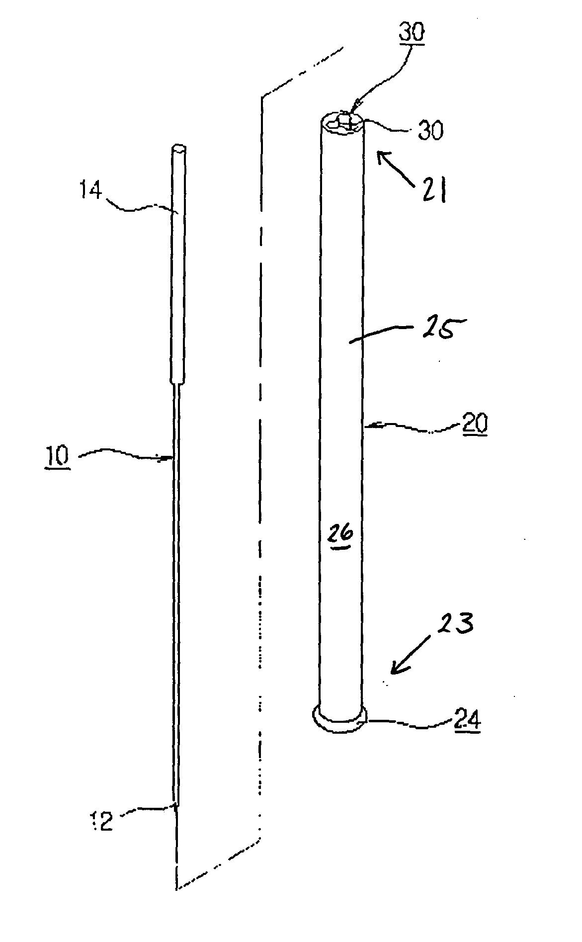
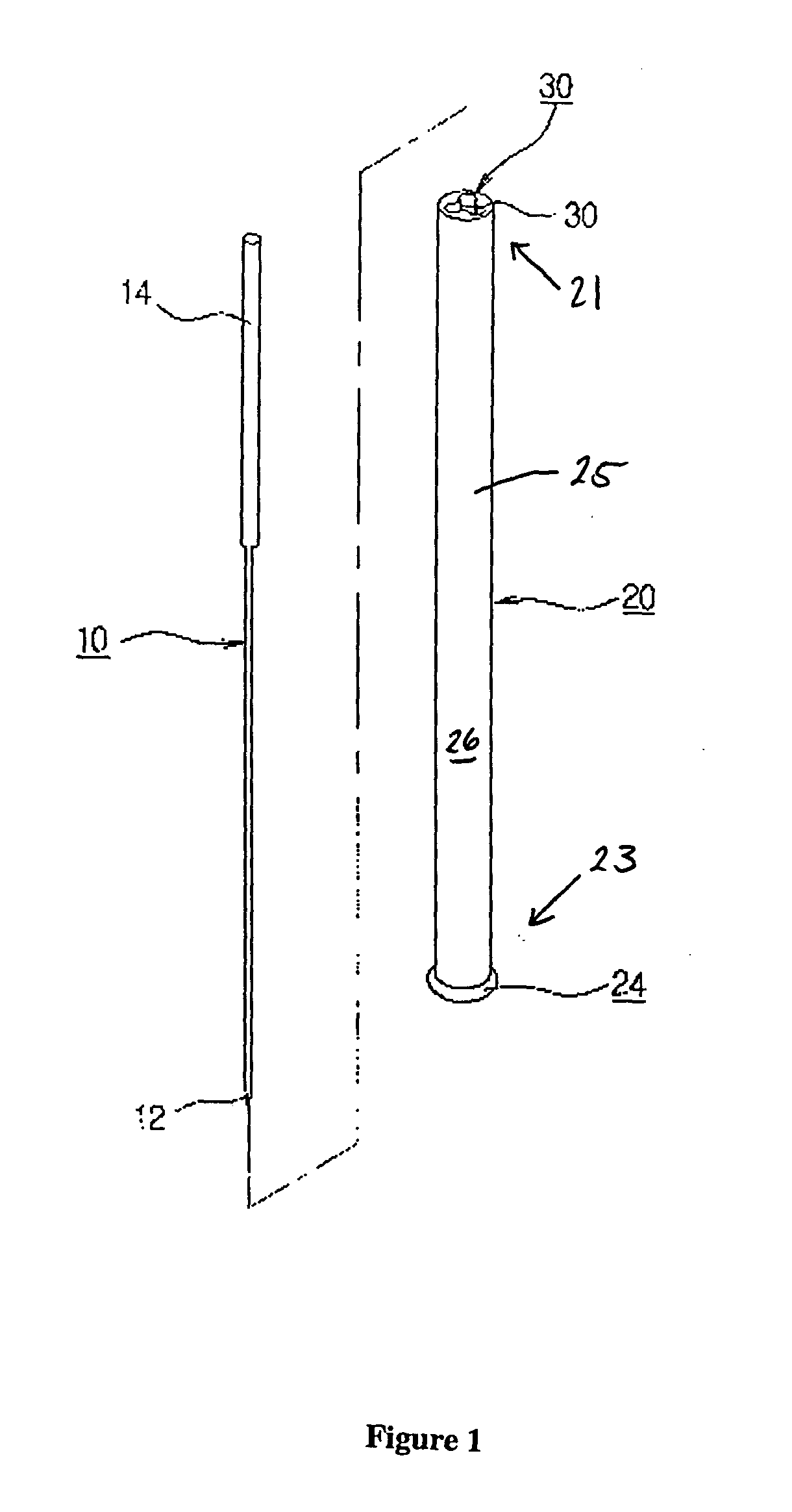
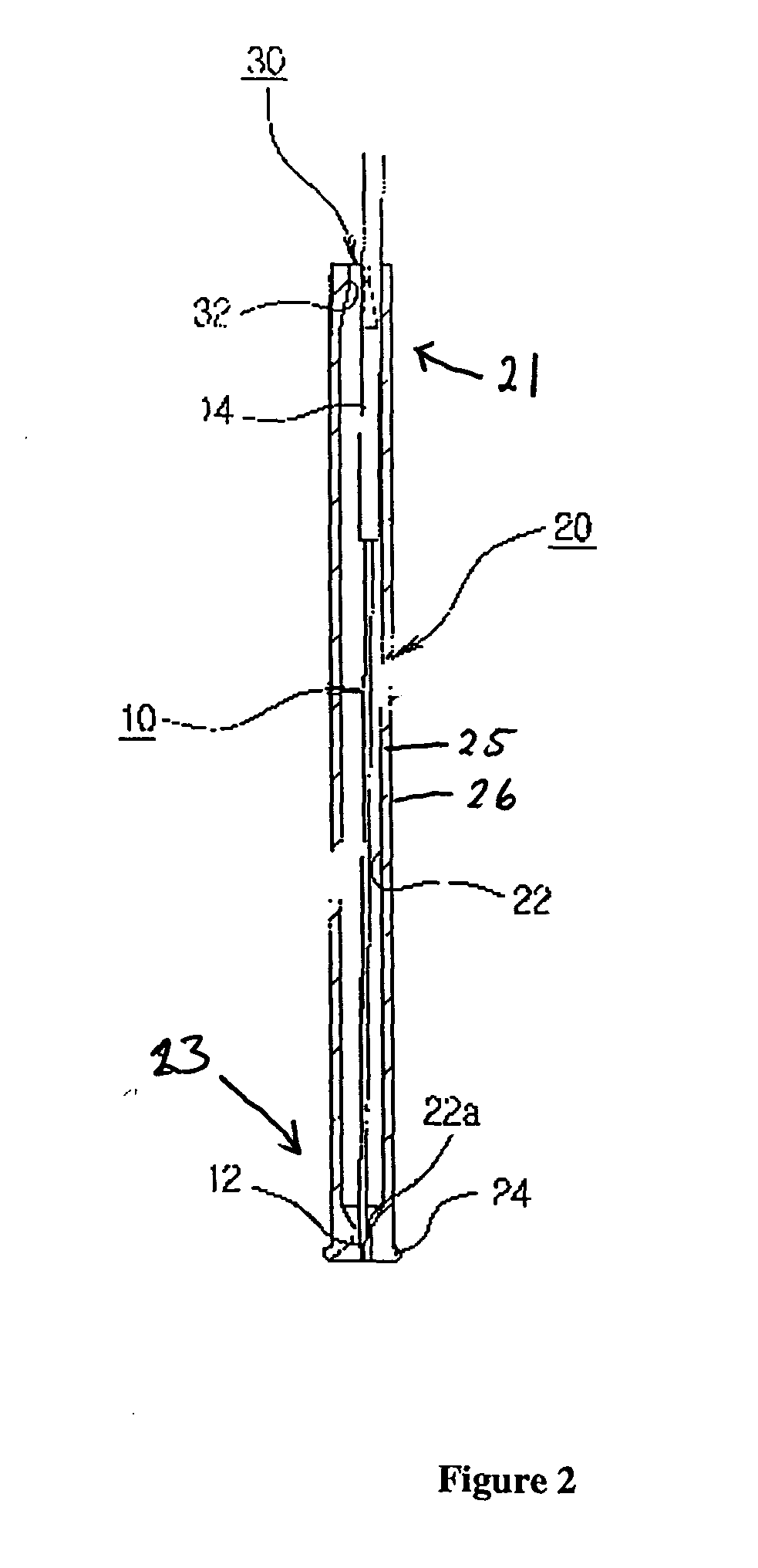
[0014] An acupuncture device according to concepts consistent with the present invention comprises an acupuncture needle 10 and a guide tube 20. Description of the needle 10 and guide tube 20 will be made with reference to the figures.
[0015] The acupuncture needle 10 is a stainless steel needle that comprises a needle body which is made of long thin stainless steel. At the distal end of the needle, there is ...
PUM
 Abstract
Description
Claims
Application Information