Self-contained electronic pressure monitoring and shutdown device

a self-contained electronic and shutdown device technology, applied in fluid pressure control, process and machine control, instruments, etc., can solve the problems of frequent preventive maintenance by highly specialized instrumentation personnel, fragile mechanisms, and high cost, and achieve the effect of minimal maintenan

Inactive Publication Date: 2005-01-27
TIMM MIGUEL A
View PDF11 Cites 9 Cited by
  • Summary
  • Abstract
  • Description
  • Claims
  • Application Information

AI Technical Summary

Benefits of technology

[0008] The Self-Contained Electronic Pressure Monitoring and Shutdown Device provides the means for a safety process shutdown that is reliable, needs minimal maintenance and provides the operator with direct reading of the process' pressure as well as the high and low pressure settings. Also, it provides a flashing lamp for each specific cause of shutdown and the means to recall the last cause of shutdown after the device has been reset. The invention is constituted of a Switch-Gauge (1) (a pressure gauge with electric contacts for high and low pressure alarms), an Electronic Logic Circuit (2), a Power Mod

Problems solved by technology

While the prior art inventions are adequate for the basic purpose and function for which they have been designed, they fail to provide a simple, reliable and ergonomic device that monitors the process' pressure and initiates shutdown when the sensed pressure falls out of the preset limits.
A number of the prior art devices have sliding seals that are prone to become frozen after some time because of lubricants drying out, creating the need for frequent preventive maintenance by highly specialized instrumentation personnel.
Another type o

Method used


Image

  • Self-contained electronic pressure monitoring and shutdown device
  • Self-contained electronic pressure monitoring and shutdown device
  • Self-contained electronic pressure monitoring and shutdown device

Examples


Embodiment Construction

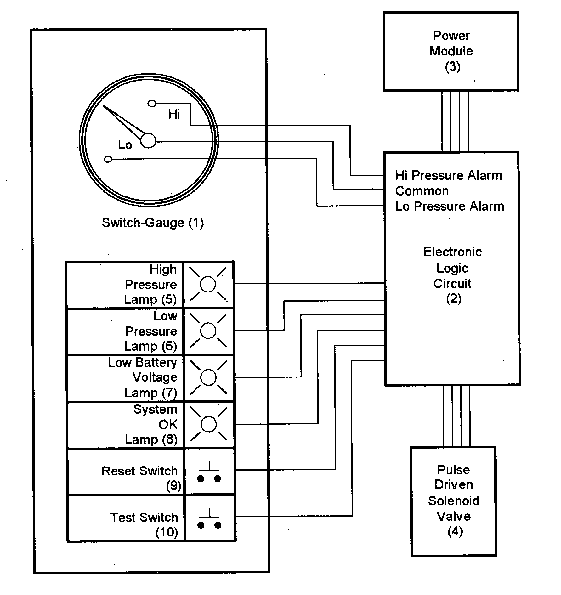
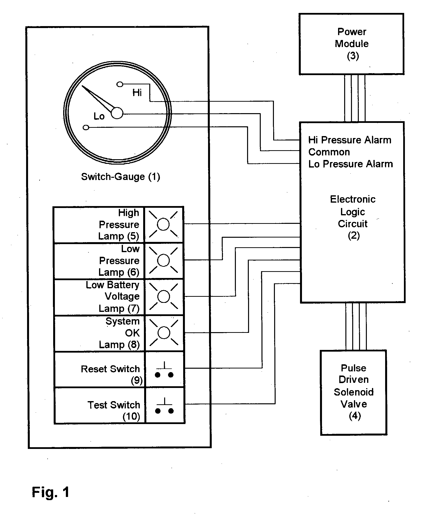
[0012] The device is composed of a Switch-Gauge (1), Electronic Logic Circuit (2), Power Module (3), High Pressure indicating lamp (5), Low Pressure indicating lamp (6), Low Battery indicating lamp (7), System OK indicating lamp (8), a momentary switch or pushbutton “Reset” (9) and a momentary switch or pushbutton “Test” (10).

[0013] When operating under normal conditions, the contacts in the Switch-Gauge (1) remain on their normally open condition and the Electronic Logic Circuit (2) remains in a routine of continuously scanning the input signals and periodically reading power voltages. The sign of life in the system is that the “System OK” lamp flashes every one or two seconds to show the operator that the system is working and no abnormal conditions have been detected.

[0014] If one of the contacts in the Switch-Gauge (1) goes from its normally open to a close condition (alarm), the Electronic Logic Circuit (2) confirms the alarm by re-scanning and re-confirming it for about one ...


PUM


Abstract

The invention is a self-contained process shutdown device that detects abnormal pressures and initiates shutdown by removing the pneumatic or hydraulic pressure needed for a given process or flow to continue. The process' pressure is detected by means of a switch-gauge (a pressure gauge with high and low alarm electrical contacts) which has a pressure sensing port connected to the monitored pressure. The contacts from the switch-gauge are connected to an electronic logic circuit that sends one or more shutdown pulses to trip a pulse driven solenoid and initiate the shutdown. This device provides indicator lamps to show statuses and alarms as well as switch or pushbuttons to activate the “Reset” and “Test” functions. The electrical power is supplied by a power module that is constituted of battery cells connected in such way that it provides a dual voltage output to feed the electronic logic separate from the pulse driven solenoid driver circuit. Alternatively, the power module may be constituted of a circuit made of a photovoltaic module, voltage regulator circuits and three main capacitors with enough capacitance to keep the electronic logic circuit and the solenoid valve driver circuit operating throughout the night or longer.

Description

CROSS REFFERENCE TO RELATED APPLICATIONS [0001] Not applicable STATEMENT REGARDING FEDERALLY SPONSORED RESEARCH OR DEVELOPMENT [0002] Not applicable BACKGROUND OF THE INVENTION [0003] The present invention relates to the field of industrial safety to shutdown a process or flow when the fluid reaches an unsafe pressure. In the event of detecting an alarm condition the invented device will provide a pneumatic or hydraulic signal to cause a safety shutdown. DESCRIPTION OF RELATED ART [0004] As shown in the reference U.S. Pat. Nos. 6,276,135; 5,213,133; 4,616,670 and 4,485,727 the prior art has an abundance of diverse process shutdown systems. [0005] While the prior art inventions are adequate for the basic purpose and function for which they have been designed, they fail to provide a simple, reliable and ergonomic device that monitors the process' pressure and initiates shutdown when the sensed pressure falls out of the preset limits. A number of the prior art devices have sliding seal...

Claims


Application Information

Patent Timeline
IPC IPC(8): F15B20/00G05D7/00
CPCF15B20/00Y10T137/0352Y10T137/0379Y10T137/1789Y10T137/2012
Inventor TIMM, MIGUEL A.
Owner TIMM MIGUEL A
Why Eureka
Try Eureka