
Computer system

a computer system and computer technology, applied in the field of computer systems, can solve the problems of overhead of lan processing, serious operational performance decline, and high cpu and input/output processing efficiency,

Inactive Publication Date: 2005-01-27
HITACHI LTD
View PDF9 Cites 52 Cited by
  • Summary
  • Abstract
  • Description
  • Claims
  • Application Information

AI Technical Summary

Benefits of technology

The present invention aims to solve the problems of conventional computer systems by reducing the overhead of accessing disk units and the load on the server and LAN. The invention is a system consisting of multiple computers and a storage subsystem connected to the computers. The storage subsystem contains multiple storage units, a management table that registers the information of each storage unit, and a control unit that manages accesses to the storage units based on the information in the management table. The management table contains the identity information of each storage unit and the addressing information of each accessing computer. The system allows for dynamic setting of the management table based on the identity information sent during the boot-up processing of each computer or by an administrator during the initial setting of the computer system. The technical effect of this invention is to provide high-speed access to disk units and reduce the load on the server and LAN.

Problems solved by technology

In the TCS as typically seen in the Network Computer System, inevitable are the overhead of the LAN processing and that of the control operation of the remote disk which occurs at both end of the NC and the server, because all disk accesses by users accompany accesses to the server via a LAN.
Therefore, it is afraid that, in the TCS, the operational performance will be decreased seriously compared to the traditional Fat Client System, wherein each Client accesses its own built-in disk unit.
Besides, because all accesses to the disk units are concentrated on the server, very high performance of CPU and Input / Output processing efficiency are required for the server, an expensive server is required to operate the Client Computer System.

Method used


Image

  • Computer system
  • Computer system
  • Computer system

Examples


Embodiment Construction

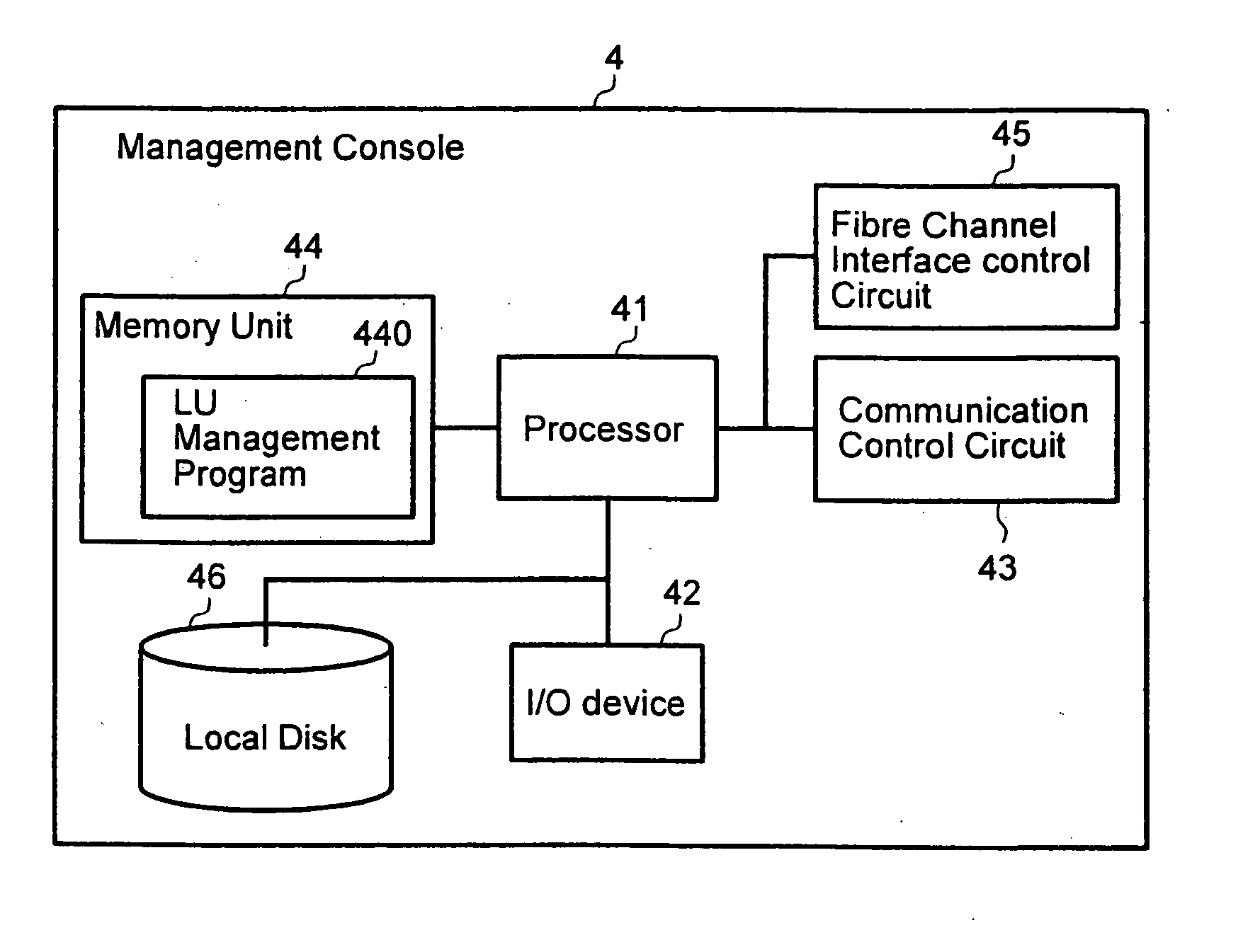
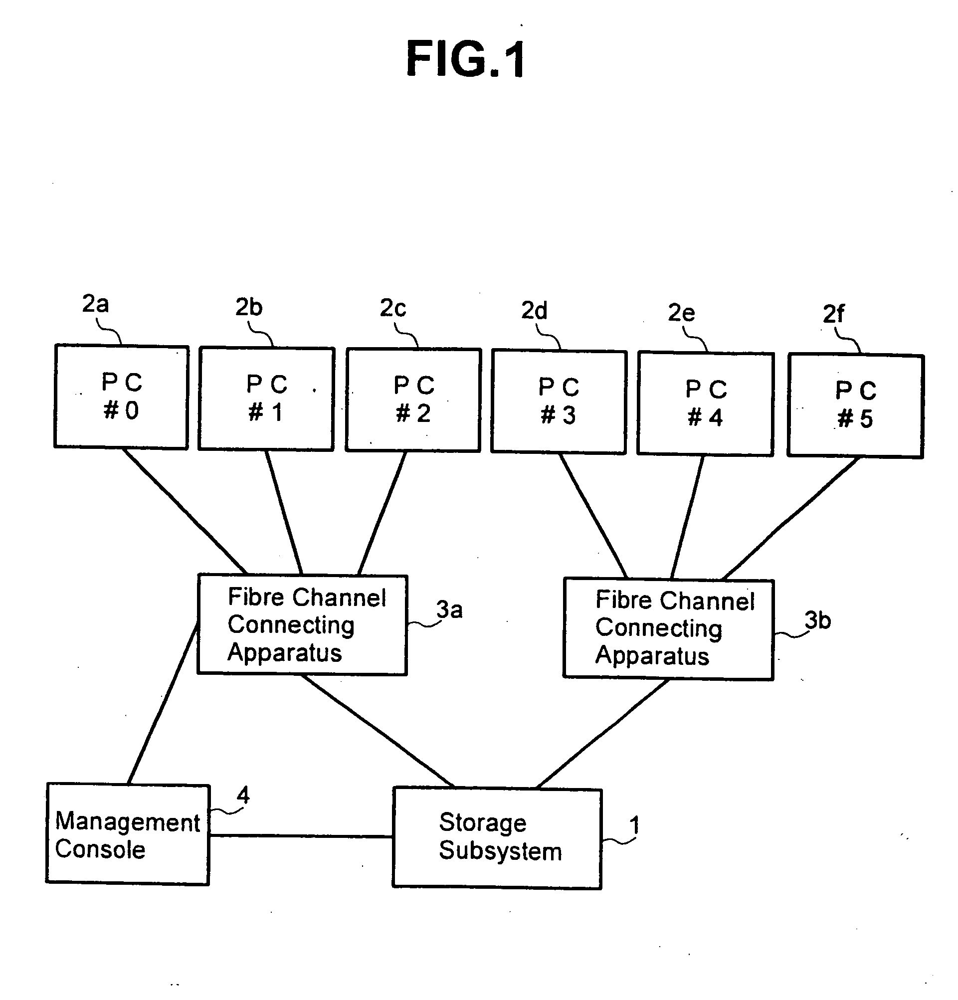
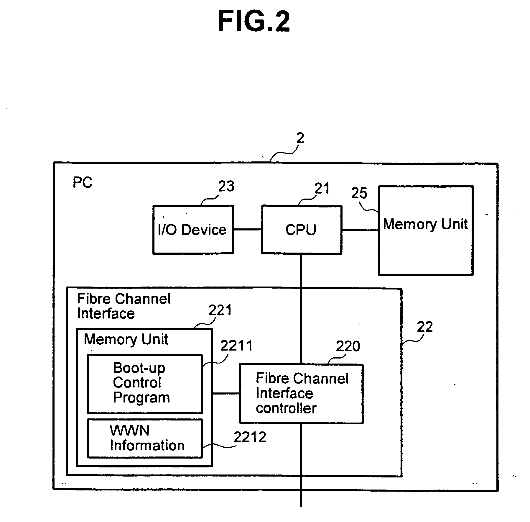
[0031]FIG. 1 is the block diagram which shows schematically the configuration of the Computer System in the 1st embodiment of the present invention. The Computer System in this embodiment has more than one Computer. In the present embodiment, so-called Personal Computers (PCs) 2a, 2b—2f are supposed to be used as the Computers. The PCs 2a, 2b—2f are the disk-less PCs which have no hard disks inside them. The PCs 2a, 2b, and 2c are connected to the Storage Subsystem 1 via the Fibre Channel Connecting Apparatus 3a, and PCs 2d, 2e, and 2f are connected to the Storage Subsystem 1 via the Fibre Channel Connecting Apparatus 3b. The Management Console 4 which is used for the management of the Computer System is connected to the Storage Subsystem 1. The Management Console 4 is also connected to the PCs 2a, 2b, and 2f via the Fibre Channel Connecting Apparatus 3a. In this embodiment example. Fibre Channel is used as the interface among the PCs, the Management Console 4, and the Storage Subsy...


PUM


Abstract

The Computer System consists of components including more than one Computer and Storage Subsystem to which more than one Computer are connected. The Storage Subsystem is equipped with more than one Storage Unit, Management Table registering information to manage Storage Units accessible by each of the Computers and Controller to control accesses by more than one Computer to more than one Storage Unit. The controller controls the accesses according to the information set in the Management Table when the Storage Unit is accessed by the Computer.

Description

BACKGROUND OF THE INVENTION [0001] This invention is related to a Computer System having more than one Computer. This invention, especially, is related to the management method for Storage Subsystem in the Computer System wherein said Storage Subsystem is shared by more than one Computers. [0002] The Computer System with which more than one user perform their business using more than one Client Computer is called a Client Computer System. Up to now, a Client Computer System is constructed with the Computers such as Personal Computers (PCs) in which all computational processings can be individually executed. The Computer which is used in such a Client Computer System is a kind of universal machine equipped with a highly efficient CPU, a large-capacity memory, large-capacity hard disk device and a high-speed graphic function, etc. and is therefore called by a popular name “Fat Client”. The Client Computer System composed of the Fat Clients is also called Fat Client System (FCS). In FC...

Claims


Application Information

Patent Timeline
Patent Type & Authority Applications(United States)
IPC IPC(8): G06F3/06G06F13/00G06F15/167G06F15/173G06F15/177
CPCG06F3/0601G06F3/0605G06F3/061G06F3/0622G06F3/0631G06F3/0637H04L67/1097G06F3/067G06F3/0683G06F15/17337G06F21/805G06F2003/0697G06F2206/1012G06F3/0665
Inventor MATSUNAMI, NAOTOYAMAMOTO, AKIRAKAMIMAKI, HIDEKIICHIKAWA, MASATOSHIMATSUMOTO, JUNMIMATSU, YASUYUKIYAGISAWA, IKUYAYAMAMOTO, MASAYUKI
Owner HITACHI LTD
Learn More