NC lathe

Active Publication Date: 2005-02-03
DMG MORI SEIKI CO LTD
View PDF11 Cites 22 Cited by
  • Summary
  • Abstract
  • Description
  • Claims
  • Application Information

AI Technical Summary

Benefits of technology

[0040] With this configuration, chips generated during workpiece machining do not fall down or accumulate onto the bed but directly drop downward, unlike the configuration of the conventional lathe. Hence, trouble wherein chips enter the guide faces provided on the bed and the accuracy of the guidance is lowered can be prevented.
[0041] Still further, the front face of the bed is formed in a vertical face, the second tool rest is moved in the first-axis direction (the horizontal direction) and the second-axis direction (the vertical direction) along the front vertical face of the b

Problems solved by technology

Because of the heavy weight of the column 116 serving as a movable body, the above-mentioned conventional NC lathe 100 has problems; that is, the load applied to a drive motor constituting a feed device (not shown) is large, the feed speed thereof cannot be raised, and the column 116 is apt to bend under the influence of inertia at the start and stop of the movement, thereby causing reduction in machining accuracy.
Hence, the size of the lower end of the bed 101 becomes large naturally, and the distances from the front end of the bed 101 to the main spindles 103 and 106 and

Method used


Image

  • NC lathe
  • NC lathe
  • NC lathe

Examples


Example

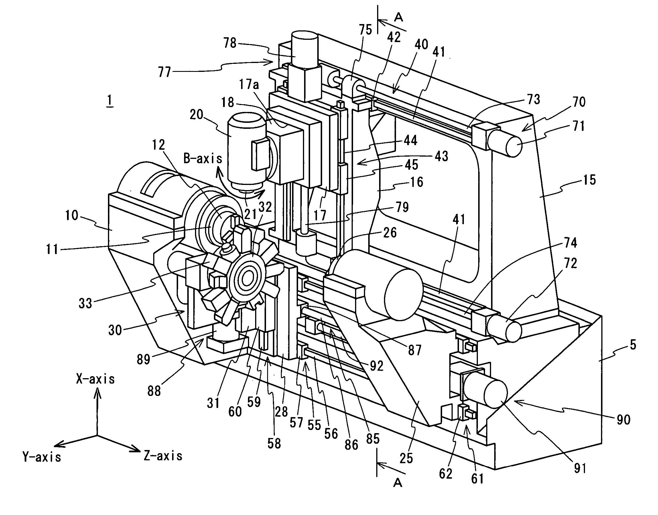
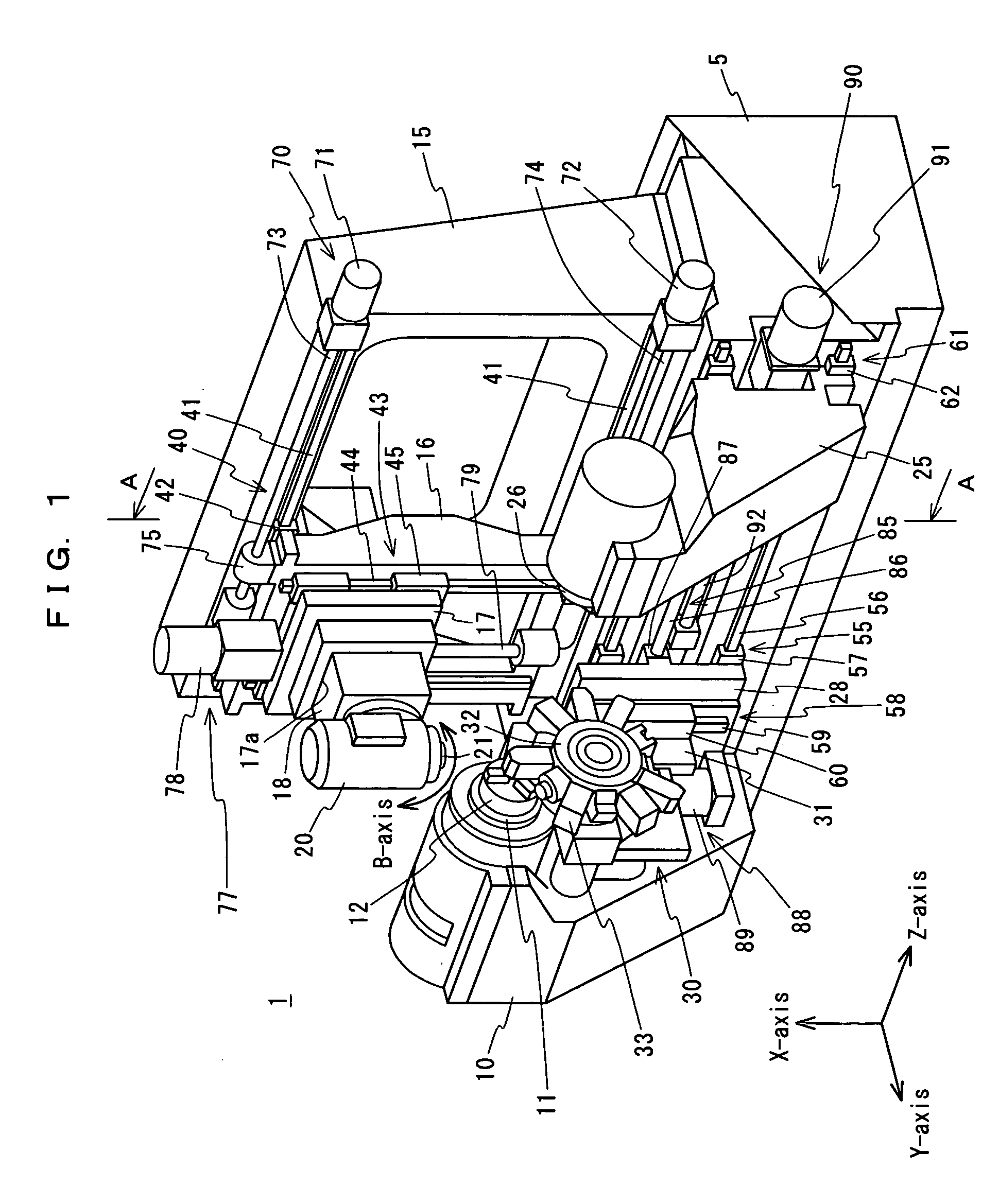
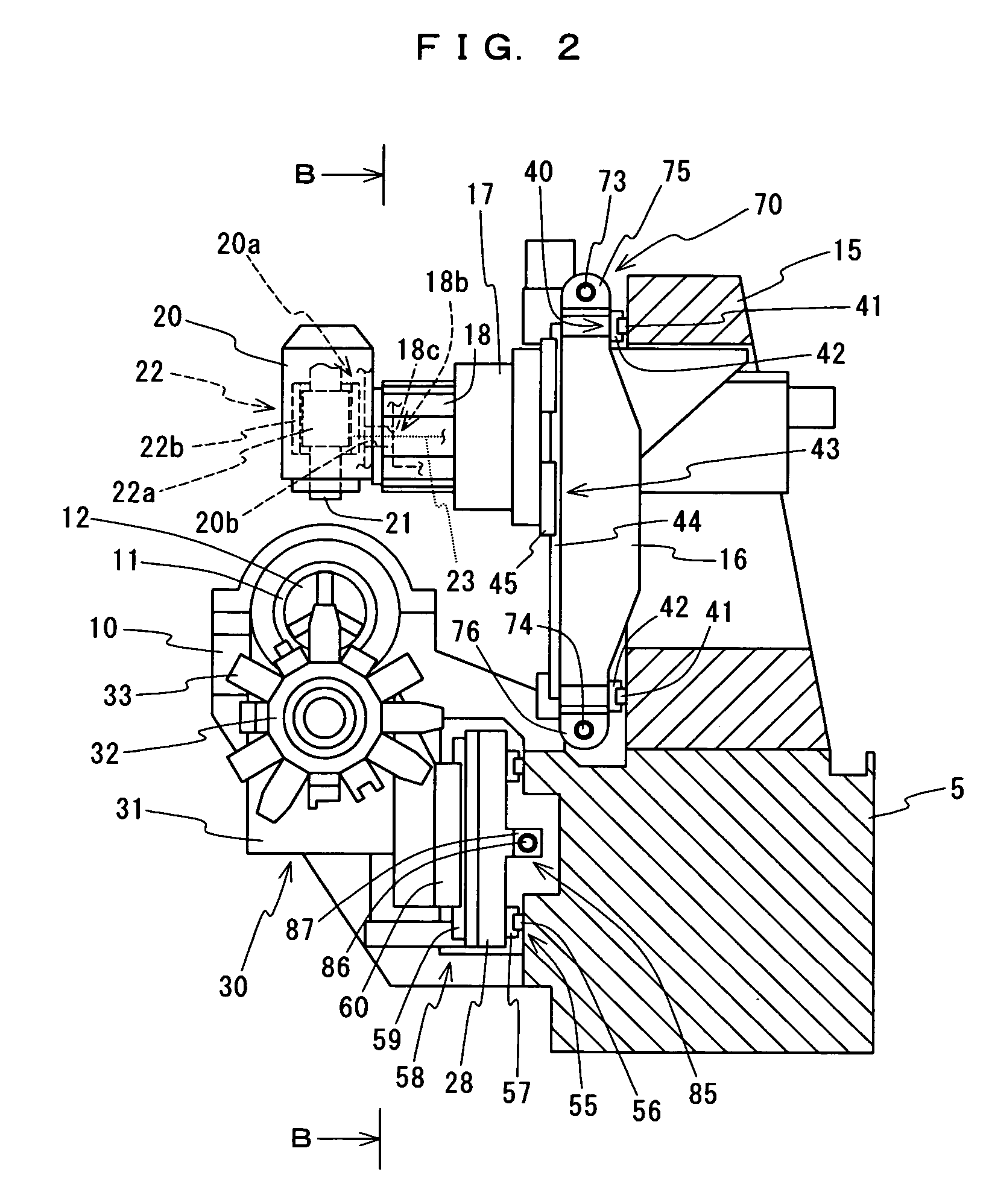
[0059] A preferred embodiment of the present invention will be described below with reference to the accompanying drawings. FIG. 1 is a perspective view showing a schematic configuration of an NC lathe in accordance with an embodiment of the present invention. FIG. 2 is a cross-sectional view taken in the arrow-indicated A-A direction of FIG. 1. FIG. 3 is a front view taken in the arrow-indicated B-B direction of FIG. 2. FIG. 4 is a cross-sectional view taken in the arrow-indicated C-C direction of FIG. 3. FIG. 5 is a cross-sectional view taken in the arrow-indicated D-D direction of FIG. 3. FIG. 6 is a cross-sectional view taken in the arrow-indicated E-E direction of FIG. 4.

[0060] As shown in FIGS. 1 to 6, the NC lathe 1 in accordance with this embodiment comprises a bed 5 formed in a rectangular shape so that the upper face is horizontal and so that the front face is vertical, a first headstock 10 provided on the front face of the bed 5, a first main spindle 11 supported by the ...


PUM

PropertyMeasurementUnit
Shapeaaaaaaaaaa

Abstract

An NC lathe 1 comprises a bed 5, a headstock 10 provided on the bed 5, a main spindle 11 supported on the headstock 10 so as to be rotatable around the axis thereof, a rotation drive device for rotating the main spindle 11, a stationary frame 15 formed in a rectangular frame shape and fixed to the upper face of the bed 5, a movable frame 16 formed in a rectangular frame shape and provided so as to be movable in the Z-axis direction with respect to the stationary frame 15, a saddle 17 provided so as to be movable in the X-axis direction with respect to the movable frame 16, a quill 18 accommodated inside the accommodation hole 17a in the saddle 17 and provided so as to be movable in the Y-axis direction, and a tool rest 20 supported on the quill 18.

Description

BACKGROUND OF THE INVENTION [0001] 1. Field of the Invention [0002] The present invention relates to an NC lathe comprising a headstock for rotatably supporting a main spindle for holding a workpiece, and a tool rest for holding a tool, the tool rest being movable in a predetermined feed direction. [0003] 2. Description of the Prior Art [0004] Conventionally, a machine tool having a structure shown in FIGS. 7 and 8 is known as an NC lathe. This NC lathe 100 comprises a bed 101 formed in the shape of a triangular prism becoming broad toward the bottom, and a first headstock 102, a second headstock 105, a first tool rest 110, a second tool rest 115 and the like provided on the bed 101 as shown in FIGS. 7 and 8 (refer to Japanese Unexamined Patent Publication No. 2002-59301). [0005] The first and second headstocks 102 and 105 rotatably support main spindles 103 and 106 around the axes thereof, respectively, and are provided with rotation drive devices (not shown) for rotating the main ...

Claims


Application Information

Patent Timeline
IPC IPC(8): B23B3/18B23B3/30B23Q1/00B23Q1/01B23Q1/62
CPCB23B3/168B23Q1/012B23Q1/626B23Q39/027Y10T409/307728Y10T82/2524Y10T82/25Y10T82/2566Y10T29/5114Y10T409/305656Y10T82/2541Y10T82/2508
Inventor TOKUMA, TSUTOMUNAKAMINAMI, MASAMITSU
Owner DMG MORI SEIKI CO LTD
Why Eureka
Try Eureka