Fuel injection control system for engine

a technology of control system and fuel injection, which is applied in the direction of electric control, fuel injecting pump, machine/engine, etc., can solve the problems of deterioration in engine so as to prevent deterioration in emission performance or drivability performance of an engine, and reduce deviation of actual injection quantity.

Active Publication Date: 2005-02-03
DENSO CORP
View PDF10 Cites 28 Cited by
  • Summary
  • Abstract
  • Description
  • Claims
  • Application Information

AI Technical Summary

Benefits of technology

[0010] It is therefore an object of th present invention to reduce deviation of actual injection quantity from command injection quantity by correcting an injection period or injection start timing in accordance with an upper limit value of charging voltage or charging speed to a piezo stack during energy changing control for changing a charging amount to the piezo element of a piezo injector. Thus, deterioration in emission performance or drivability performance of an engine can be prevented.
[0011] According to an aspect of the present invention, charging amount changing means changes an upper limit value of charging voltage applied to a piezo element of a piezo injector in accordance with fuel pressure detected by fuel pressure detecting means. Then, a command injection period is calculated at least based on command injection quantity and the upper limit value of the charging voltage applied to the piezo element changed by charging amount changing means. The command injection quantity is set in accordance with an operating state or operating condition of an engine. Thus, change in a discharging period of the piezo element from an end time point of the command injection period to another time point at which the piezo element contracts by an arbitrary degree decreases even if energy changing control for changing the charging amount to the piezo element is performed. More specifically, even if the upper limit value of the charging voltage applied to the piezo element is changed in accordance with the fuel pressure, the change in the timing when the piezo element contacts by an arbitrary degree, closing timing of a nozzle portion or injection end timing of the piezo injector can be reduced. Thus, deviation of the actual injection quantity of the fuel injected to the engine from the command injection quantity can be reduced.
[0012] According

Problems solved by technology

Moreover, emission performance or drivability

Method used


Image

  • Fuel injection control system for engine
  • Fuel injection control system for engine
  • Fuel injection control system for engine

Examples


first embodiment

[0024] (First Embodiment)

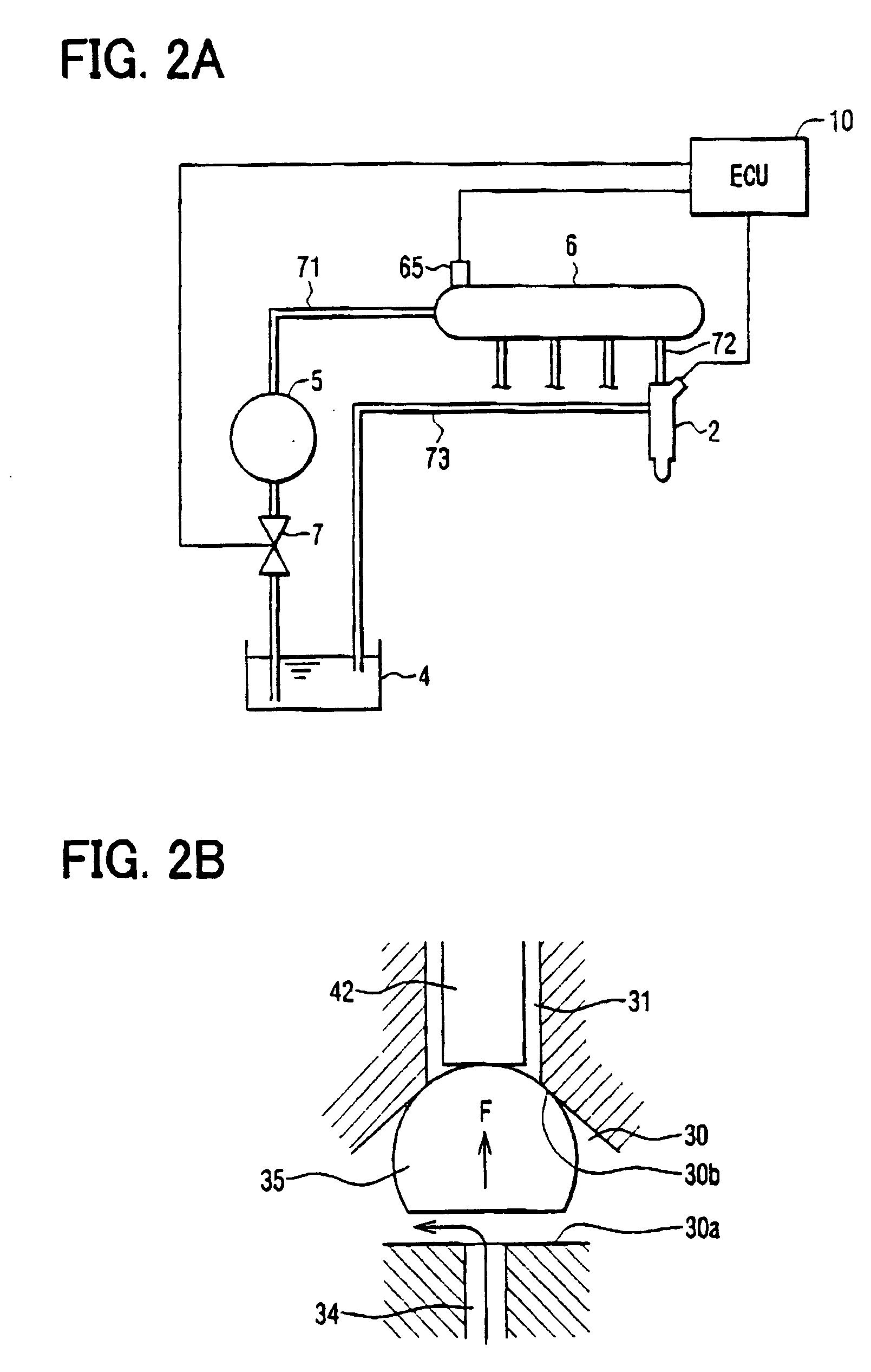
[0025] Referring to FIG. 2A, a common rail type fuel injection system having a piezo injector 2 according to the first embodiment is illustrated.

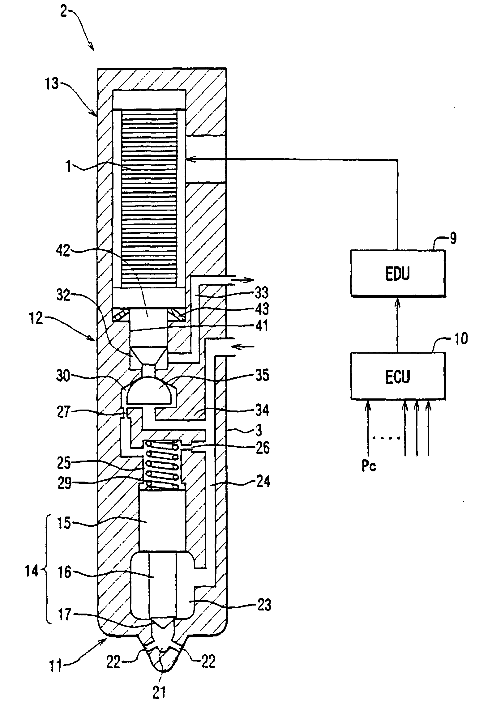
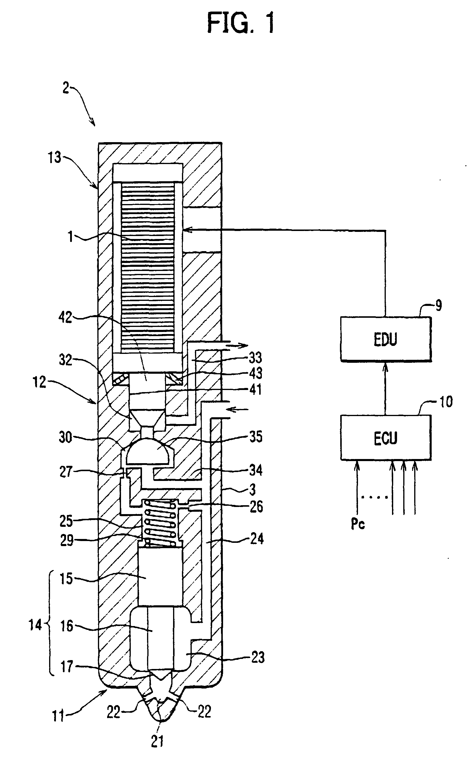
[0026] A piezo element (piezo stack) 1 of the embodiment is accommodated in a rod member 3 of the piezo injector 2 as shown in FIG. 1. The piezo injector 2 is mounted on each cylinder of an internal combustion engine such as a multi-cylinder diesel engine. Thus, the piezo element 1 functions as a piezo actuator for switching between a performing state and a stopping state of fuel injection. The piezo stack 1 has a layered structure in which a multiplicity of piezo plates is stacked with electrodes in a vertical direction in FIG. 1. The piezo stack 1 extends when it is charged, and contracts when it is discharged.

[0027] The piezo injector 2 in which the piezo stack 1 is mounted is applied to a common rail type fuel injection system, for instance. The common rail type fuel injection system has the plurality of piezo...

second embodiment

[0059] (Second Embodiment)

[0060] Next, a method for controlling the injection period (the injection quantity) and the injection timing of the piezo injector 2 according to the second embodiment will be explained based on a flowchart shown in FIG. 5.

[0061] If the ignition switch is switched on (IG ON), like the first embodiment, the common rail pressure Pc detected by the common rail pressure sensor 65 is inputted, and the upper limit value of the charging voltage, or the target energy Et, to the piezo stack 1 is calculated based on the common rail pressure Pc by a map search and the like in Step S11 (charging amount changing means). The target energy Et is increased as the common rail pressure Pc increases as shown in FIG. 5.

[0062] Then, the target energy Et calculated in Step S11 is commanded to the EDU 9 in Step S12. Then, the command injection period TQFIN for each target energy Et is calculated based on a characteristic map, which is made through experimentation and the like b...

third embodiment

[0064] (Third Embodiment)

[0065] Next, a method for controlling the injection period (the injection quantity) and the injection timing of the piezo injector 2 according to the third embodiment will be explained based on a flowchart shown in FIG. 6.

[0066] In the third embodiment, as a method for changing the charging amount to the piezo stack 1, a method for changing charging speed of the charging voltage applied to the piezo stack 1 of the piezo injector 2 is employed.

[0067] First, the target energy Et to the piezo stack 1 corresponding to the common rail pressure Pc is calculated and commanded to the EDU 9 in Step S1. Then, the charging amount to the piezo stack 1 (charging speed of the charging voltage applied to the piezo stack 1), or charging current Cc to the piezo stack 1, is calculated based on the target energy Et by a map search and the like in Step SB. The charging current Cc to the piezo stack 1 is increased as the target energy Et to the piezo stack 1 increases as shown...


PUM


Abstract

An engine control unit (ECU) of an internal combustion engine performs energy changing control for changing a charging amount (an upper limit value of charging voltage, charging speed or target energy) to a piezo stack of a piezo injector in accordance with common rail pressure. During the energy changing control, the ECU contracts a command injection period as the target energy charged to the piezo stack increases so that actual injection end timing or valve closing timing of a nozzle portion is unchanged even if the target energy is changed. Meanwhile, the ECU delays command injection timing as the target energy increases so that actual injection start timing or valve opening timing of the nozzle portion is unchanged even if the target energy is changed.

Description

CROSS REFERENCE TO RELATED APPLICATION [0001] This application is based on and incorporates herein by reference Japanese Patent Application No. 2002-237811 filed on Aug. 19, 2002. BACKGROUND OF THE INVENTION [0002] 1. Field of the Invention [0003] The present invention relates to a fuel injection control system for controlling quantity and timing of fuel injection into cylinders of an internal combustion engine such as a diesel engine. Specifically, the present invention relates to a fuel injection control system capable of performing energy changing control for changing a charging amount to a piezo element of a piezo injector. [0004] 2. Description of Related Art [0005] A common rail type fuel injection system is used in a diesel engine. In the common rail type fuel injection system, a high-pressure supply pump pressure-feeds high-pressure fuel to a common rail, which is common to respective cylinders. Thus, the common rail accumulates the high-pressure fuel. The high-pressure fuel...

Claims


Application Information

Patent Timeline
IPC IPC(8): F02M47/00F02B3/06F02D41/04F02D41/20F02D41/38F02D41/40F02M47/02F02M51/06F02M59/46F02M63/02
CPCF02B3/06F02D41/2096F02D41/3809F02D41/3836F02M63/0225F02D2041/389F02D2200/0602F02M47/027F02M59/468F02D2041/2051
Inventor TAKEMOTO, EIJI
Owner DENSO CORP
Why Eureka
Try Eureka