Absorption heat-transfer system

a heat exchange system and heat exchange technology, applied in the operation mode of machines, refrigeration components, lighting and heating apparatuses, etc., can solve the problems of limited flow rate of heat exchange machines, limited waste heat recovery system, and inability to recover waste heat, so as to reduce the inlet pressure

Inactive Publication Date: 2005-02-03
COOLING TECH
View PDF13 Cites 48 Cited by
  • Summary
  • Abstract
  • Description
  • Claims
  • Application Information

AI Technical Summary

Benefits of technology

[0027] A refrigerant flow control device comprises 1) a thermal expansion valve that receives refrigerant from a first line connected to the condenser and passes the refrigerant to the evaporator in a second line, and 2) a fixed restrictor located in the first line between the condenser and the thermal expansion valve to reduce the inlet pressure to the thermal expansion valve.

Problems solved by technology

In the past, waste heat stream recovery systems have been limited to the recovery of waste heat for relatively low temperature processes, e.g., space heating, parts cleaning, and operation of heat exchangers that require an operational temperature of less than 250° F.
As such, previous absorption, heat-exchange machines have been limited typically to a low-temperature lithium bromide-water solution pair as the working solution.
Unfortunately such devices present a problem in that the flow rate may be lower than desired during low ambients (reduced high-side pressure) or higher than desired during high ambients (increased high side pressure).
Thermal expansion valves, which vary the refrigerant flow rate, exacerbate the problem as the valve attempts to maintain an even low-side pressure.
Similar type problems exist with respect to refrigerant flow valves located between the high-pressure condenser and the low pressure evaporator.
Although thermal expansion valves are available for vapor-compression systems, these valves perform poorly in absorption systems because of their low high-low side differential operating pressure.
Any attempt at using an oversized vapor-compression system valve results in a poorly functioning valve with poor control characteristics.
Use of a smaller valve that does not match the absorption system capacity results in higher fluid velocities that lead to premature valve failure.

Method used


Image

  • Absorption heat-transfer system
  • Absorption heat-transfer system
  • Absorption heat-transfer system

Examples


Embodiment Construction

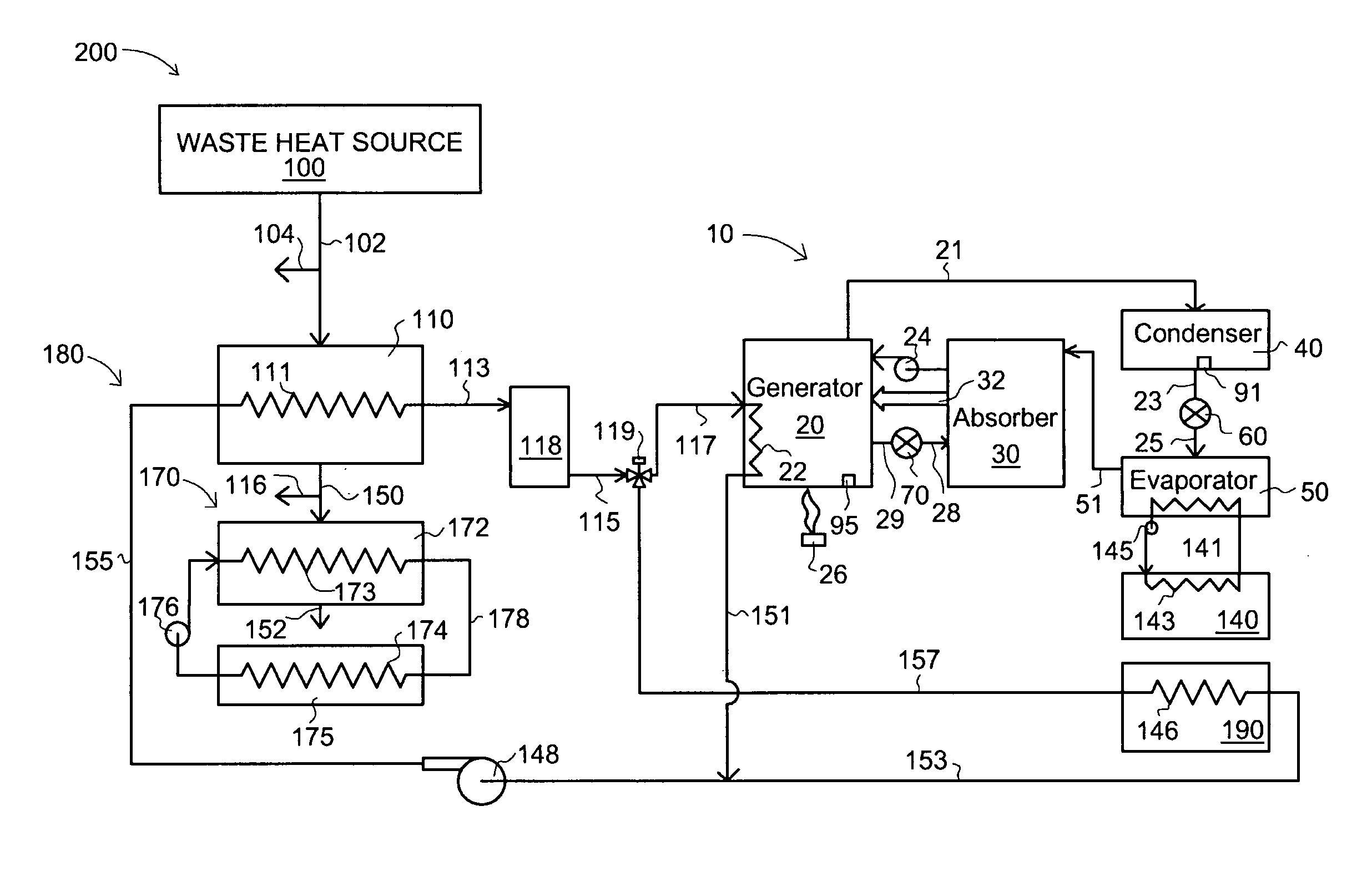
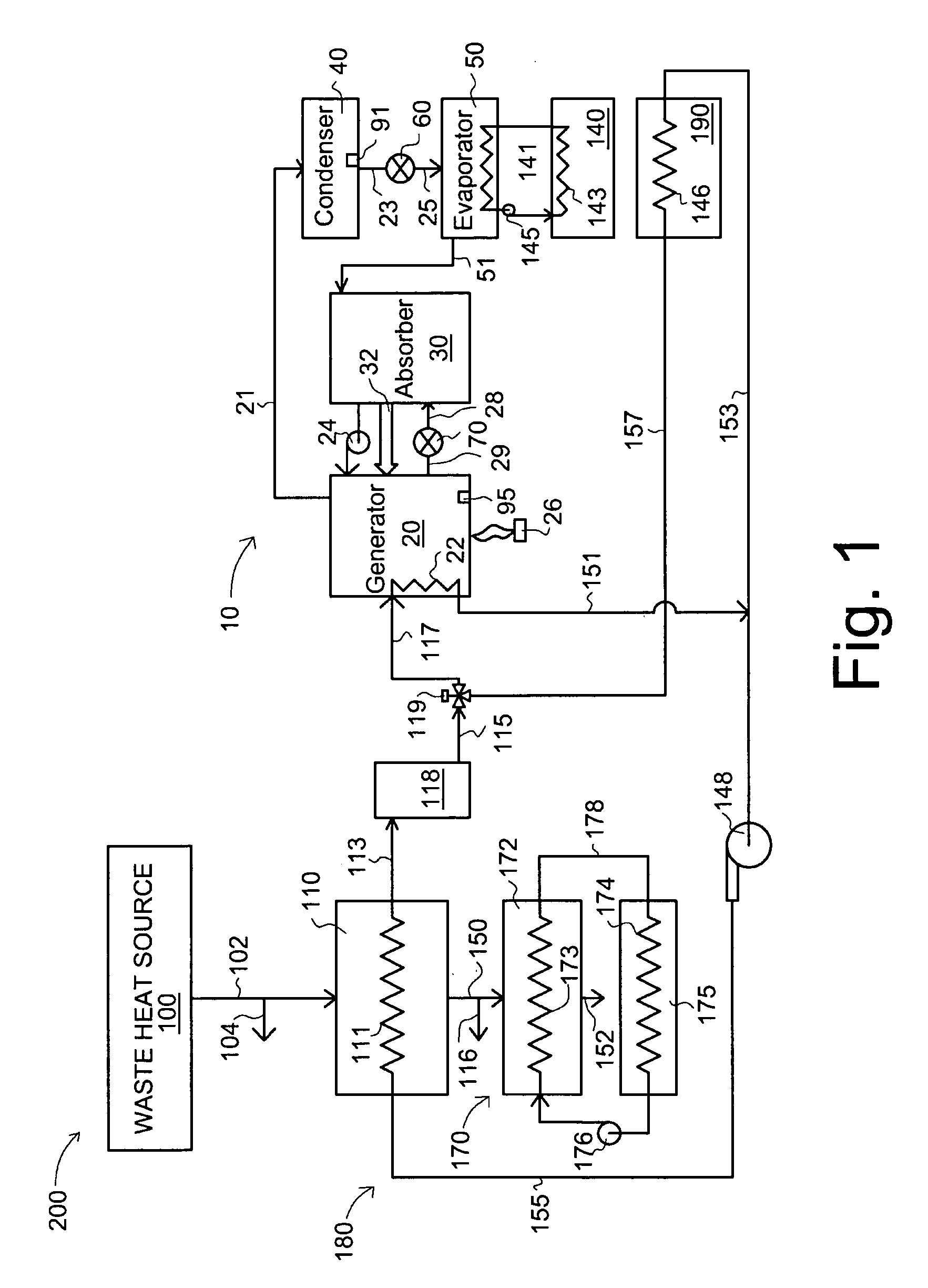
[0038] With reference to the drawings and initially FIG. 1, a waste-heat recovery, heat-transfer device 200 comprises an absorption heat-transfer machine 10 for operation by means of a waste heat source 100 at working-solution (solution pair) temperatures in generator 20 of greater than 250° F. (121° C.). In its basic form, the absorption heat-transfer machine 10 comprises an interconnected generator 20, an absorber, 30, a condenser 40, and an evaporator 50. Expansion (flow control) devices 60, 70 control the flow of fluids from a high pressure to a low pressure component Specifically flow control device 60 controls the flow of refrigerant from the high-pressure condenser 40 to the low-pressure evaporator 50. Flow control device 70 controls the flow of weak solution from the high-pressure generator 20 to the low pressure absorber 30. Solution pump 24 provides strong solution from the absorber 30 to the generator 20.

[0039] In operation, a high-temperature solution pair (also here te...


PUM


Abstract

A waste heat source (100) is used to heat a high temperature heat transfer fluid which is used to heat an absorption heat transfer machine (10) having a generator (20), an absorber (30), a condenser (40), and an evaporator (50) operatively connected together. The high temperature heat transfer fluid can also be used to heat a load (190) such as a room space or a process. The waste heat source (100) can also be used to heat an intermediate heat transfer fluid, which can be used to heat a second load (175) such as a space, a process, or an absorption heat transfer machine. Novel flow control devices (70, 60) for controlling the flow of weak solution from generator (20) to absorber (30) or of refrigerant from condenser (40) to evaporator (50), respectively, are also described.

Description

PRIOR APPLICATION [0001] This application claims of benefit of U.S. Provisional Application Ser. No. 60 / 336094, filed Nov. 30, 2001, all of which is incorporated herein by reference as if completely written herein.BACKGROUND OF THE INVENTION [0002] 1. Field of the Invention [0003] This invention pertains to absorption heat-exchange systems and more particularly to high-temperature waste heat recovery systems and to control of weak solution and refrigerant flow in absorption heat-exchange systems. [0004] 2. Background of the Invention [0005] In the past, waste heat stream recovery systems have been limited to the recovery of waste heat for relatively low temperature processes, e.g., space heating, parts cleaning, and operation of heat exchangers that require an operational temperature of less than 250° F. (121° C.). As such, previous absorption, heat-exchange machines have been limited typically to a low-temperature lithium bromide-water solution pair as the working solution. [0006] ...

Claims


Application Information

Patent Timeline
Patent Type & Authority Applications(United States)
IPC IPC(8): F25B15/04F25B27/02F25B29/00F25B41/04F25B41/06
CPCF25B15/04F25B27/02F25B29/006F25B41/04Y02B30/625F25B41/062F25B2333/003F25B2333/007F25B2400/0411F25B41/06Y02A30/274Y02P80/15F25B41/31F25B41/28
Inventor GARRABRANT, MICHAEL A.STOUT, ROGER E.KLINTWORTH II, MICHAEL W.COLLET, ERIC
Owner COOLING TECH
Why Eureka
Try Eureka