Gas sensor with sensing particle receptacles

Inactive Publication Date: 2005-02-03
HON HAI PRECISION IND CO LTD
View PDF9 Cites 4 Cited by
  • Summary
  • Abstract
  • Description
  • Claims
  • Application Information

AI Technical Summary

Benefits of technology

[0014] In summary, the receptacles receive sensing particles of the sensing layer. The sensing particles are physically divided into several connected parts by th

Problems solved by technology

This reduces the capability for

Method used


Image

  • Gas sensor with sensing particle receptacles
  • Gas sensor with sensing particle receptacles
  • Gas sensor with sensing particle receptacles

Examples


Example

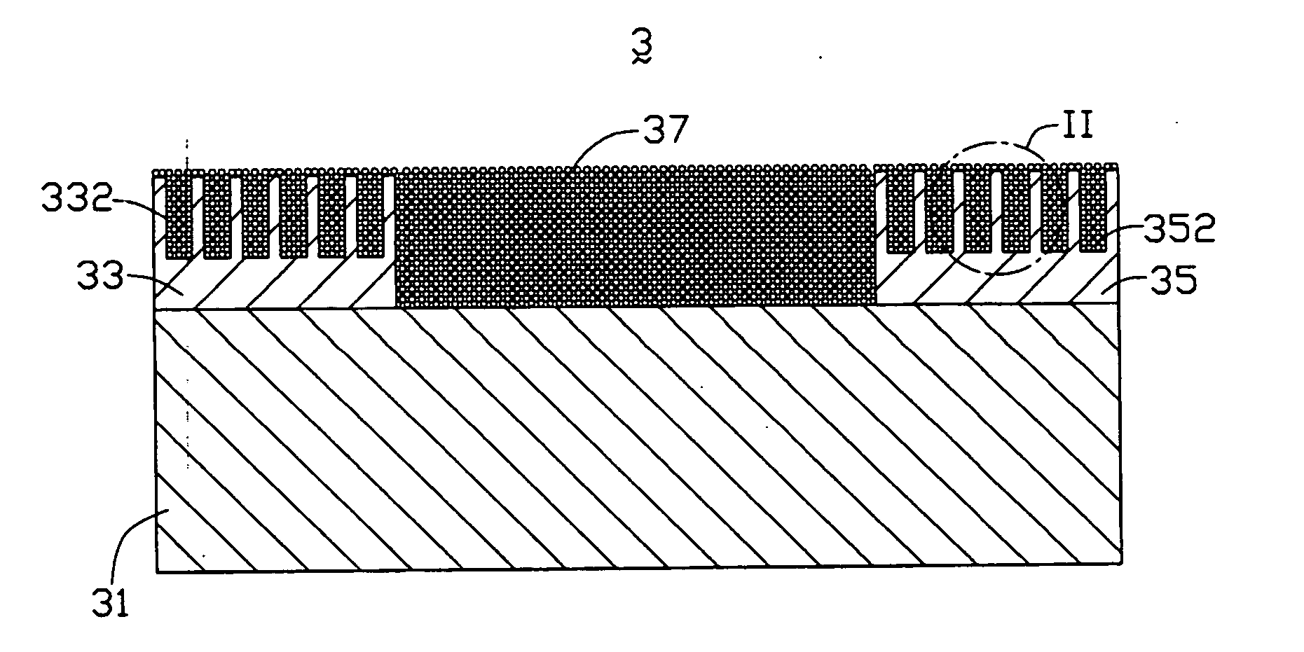
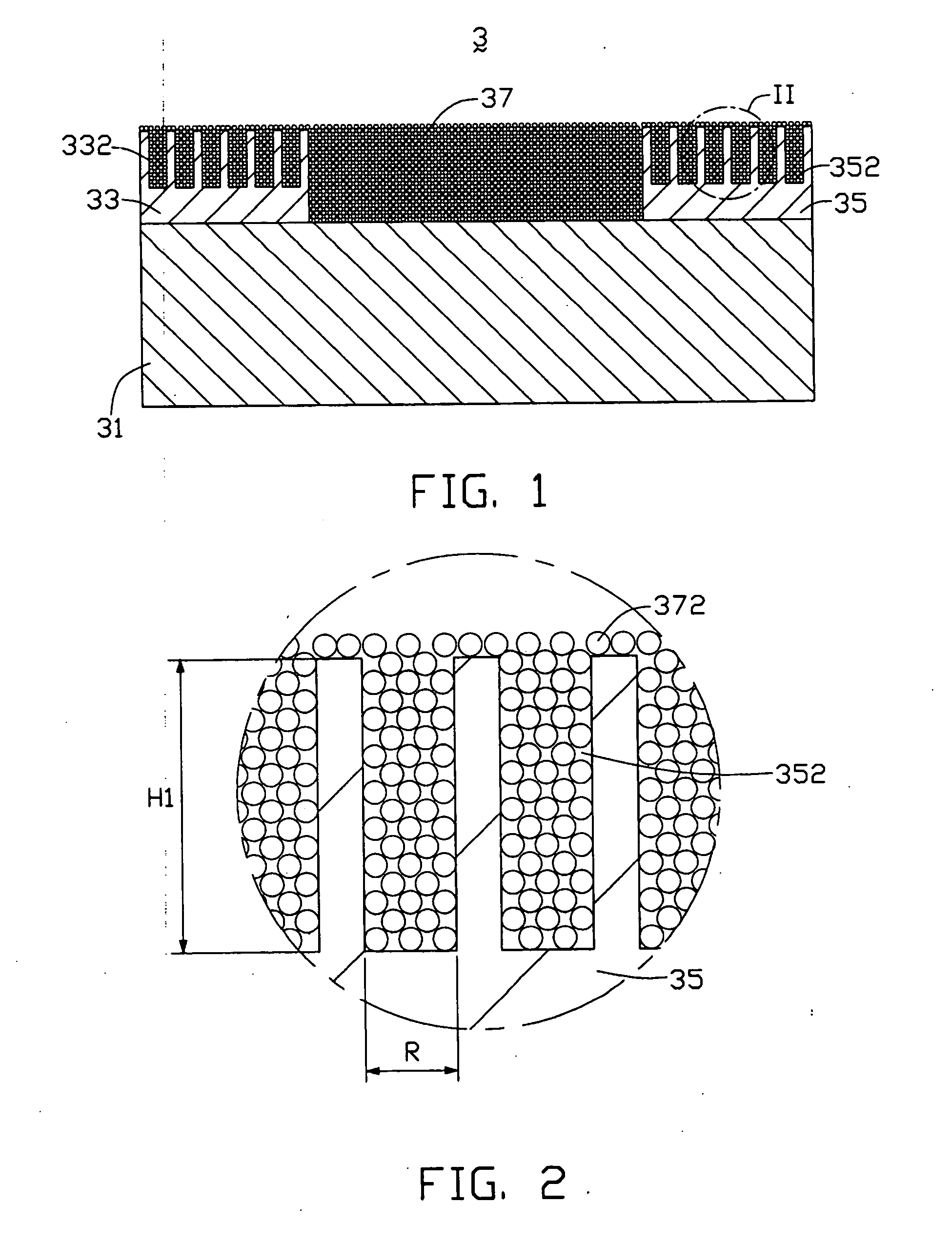
[0020] With reference to FIG. 1, there is shown a gas sensor 3 for detecting the presence of a gas in accordance with a preferred embodiment of the present invention. The gas sensor 3 comprises an insulating substrate 31, two separated electrodes 33, 35, and a sensing layer 37 formed on the substrate 31 and electrodes 33, 35. Each electrode 33, 35 defines a plurality of blind holes 332, 352 respectively. The sensing layer 37 covers surfaces of the electrodes 33, 35, and contains a plurality of sensing particles 372. Some sensing particles 372 are received in the blind holes 332, 352.

[0021] The insulating substrate 31 is a thin sheet or film, and is generally made of an insulating material such as quartz, a ceramic material, silicon nitride or the like. Further, the insulating material of the insulating substrate 31 preferably has a high thermal conductivity. This is because the gas sensor 3 needs to be heated in the process of manufacturing, and usually operates at high temperature...


PUM


Abstract

A gas sensor (3) includes an insulating substrate (31), two electrodes (33, 35) formed thereon, and a sensing layer (37) formed on the insulating substrate and the electrodes. Each electrode defines a plurality of receptacles (332, 352) adjacent a surface thereof The sensing layer contains a plurality of sensing particles (372). A portion of the sensing particles is received in the receptacles. The sensing particles are physically divided into several connected parts by the receptacles, and accordingly are highly dispersed. Thereby, more spaces among the sensing particles are provided, for improving the sensitivity of the gas sensor.

Description

BACKGROUND OF THE INVENTION [0001] 1. Field of the Invention [0002] The present invention relates generally to sensors for use in gas-reactive applications, and more particularly to gas sensors having sensing layers containing oxide-semiconductor particles. [0003] 2. Description of Related Art [0004] Gas sensors for detecting oxidizing and reducing gases, such as O2, CO2, CO, SO2 or H2, are employed in numerous Applications relating to personal safety, industrial process control and environmental protection. As one example, gas sensors are used in modern automobiles to provide exhaust emission feedback control as well as to monitor the performance of components such as the fuel injection system, the exhaust gas recirculation valve, and the catalytic converter. [0005] A common type of gas sensor uses an oxide-semiconductor as a sensing layer. The gas sensor operates on the principle that absorption of a detected gas on a surface of the sensing layer causes a change in a conductive co...

Claims


Application Information

Patent Timeline
IPC IPC(8): G01N27/00G01N27/26G01N33/00G08B23/00
CPCG01N33/0031
Inventor HUANG, WEN-JENGHUANG, CHUAN-DE
Owner HON HAI PRECISION IND CO LTD
Why Eureka
Try Eureka