Method and apparatus for illuminating a field-of-view and capturing an image

Active Publication Date: 2005-02-03
MICROVISION
View PDF26 Cites 232 Cited by
  • Summary
  • Abstract
  • Description
  • Claims
  • Application Information

AI Technical Summary

Benefits of technology

[0013] In its various aspects, the present invention relates to imaging systems, to laser scanners, and to illumination systems that automatically create variable intensity illumination across the field-of

Problems solved by technology

In such situations, peak power consumption and illuminator cost vs.
Unfortunately, flash photography suffers from dynamic range issues, having a tendency to overexpose nearby objects while underexposing distant parts of the FOV.
Often, the resulting ima

Method used


Image

  • Method and apparatus for illuminating a field-of-view and capturing an image
  • Method and apparatus for illuminating a field-of-view and capturing an image
  • Method and apparatus for illuminating a field-of-view and capturing an image

Examples


Embodiment Construction

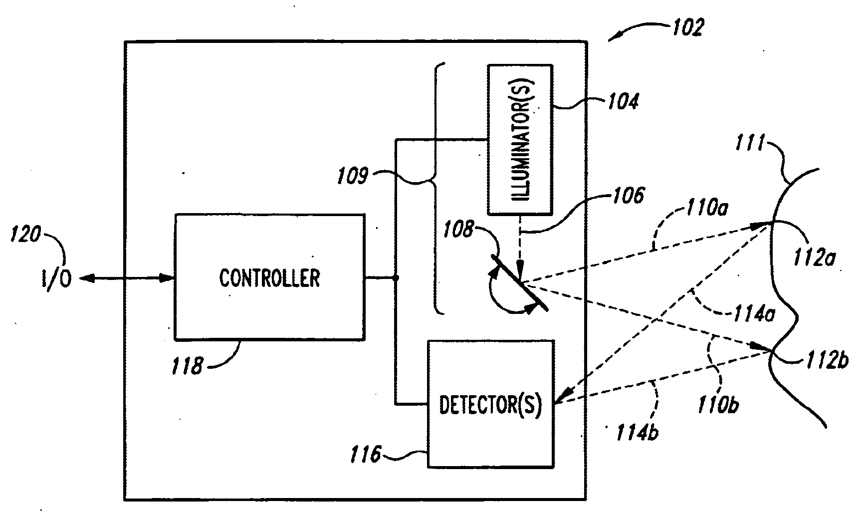
[0065]FIG. 1 shows a block diagram of a scanned beam imager 102 that comprises one form of a variable illumination system. An illuminator 104 creates a first beam of light 106. A scanner 108 deflects the first beam of light across a field-of-view (FOV) to produce a second scanned beam of light 110. Taken together, the illuminator 104 and scanner 108 comprise a variable illuminator 109. Instantaneous positions of scanned beam of light 110 may be designated as 110a, 110b, etc. The scanned beam of light 110 sequentially illuminates spots 112 in the FOV. Spots 112a and 112b in the FOV are illuminated by the scanned beam 110 at positions 110a and 110b, respectively. While the beam 100 illuminates the spots, a portion of the illuminating light beam 100 is reflected according to the properties of the object or material at the spots to produce scattering or reflecting the light energy. A portion of the scattered light energy travels to one or more detectors 116 that receive the light and pr...


PUM


Abstract

A variable illuminator, for instance a device for scanning a beam of light, emits a selected amount of power to a plurality of spots across a field of view. The amount of power is determined as inversely proportional to the apparent brightness of each spot. In the case where the spot size is equal to pixel size, the device may operate with a non-imaging detector. In the case where pixel size substantially equals spot size, the output of the variable illuminator may be converged to produce a substantially uniform detector response and the image information is determined as the inverse of a frame buffer used to drive the variable illuminator. The illuminator and detector may be driven synchronously. In the case where an imaging detector is used, the variable illumination may be used to compress the dynamic range of the field of view to substantially within the dynamic range of the imaging detector.

Description

FIELD OF THE INVENTION [0001] The present invention relates to scanned beam systems and variable illumination systems, and more particularly to control systems for scanned beam imagers and variable illuminators. BACKGROUND OF THE INVENTION [0002] The field of imaging can be divided into one-dimensional (1 D) or linear imaging, two-dimensional (2 D) imaging, and three-dimensional imaging. [0003] Examples of 1 D imagers include bar code devices using linear pixelated detectors, including for instance charge-coupled-device (CCD) and complementary-metal-oxide-silicon (CMOS) detectors. Linear pixelated imagers typically include illumination to reduce exposure time and ambient lighting requirements, often in the form of a sheet of light formed by a light emitting diode (LED) or LED array. Line-Scan cameras are a specific type of 1 D pixelated imager. In line-scan cameras, a second dimension, usually perpendicular to the detector array, is provided by movement of the object or phenomenon b...

Claims


Application Information

Patent Timeline
IPC IPC(8): G06K7/10
CPCG06K7/10851G06K7/10564
Inventor WIKLOF, CHRISTOPHER A.TEGREENE, CLARENCE T.
Owner MICROVISION
Why Eureka
Try Eureka