IC card and IC chip module

a technology of ic cards and chips, applied in the field of ic cards and ic chip modules, can solve the problems of unable to find the function of ic cards, difficult to obtain important data, and insufficient normal operation of the ic circuit, so as to reduce the cost of manufacturing and enhance data security

Inactive Publication Date: 2005-02-03
ROHM CO LTD
View PDF7 Cites 43 Cited by
  • Summary
  • Abstract
  • Description
  • Claims
  • Application Information

AI Technical Summary

Benefits of technology

[0041] As such, the exposure detection unit is hardly recognized in the geometry of the IC chip, resulting in an enhanced data security. Furthermore, incorporating a portion or the entirety of the exposure detection unit into the IC chip in fabricating the IC chip can reduce the cost for manufacturing the IC card or the IC chip module.

Problems solved by technology

As such, when the housing body housing the IC card is opened the IC circuit does not operate normally.
Thus, if the IC card is improperly obtained and opened, it is extremely difficult to find the function of the IC card.
Thus it is extremely difficult to obtain important data when the IC card is improperly opened.

Method used


Image

  • IC card and IC chip module
  • IC card and IC chip module
  • IC card and IC chip module

Examples


first embodiment

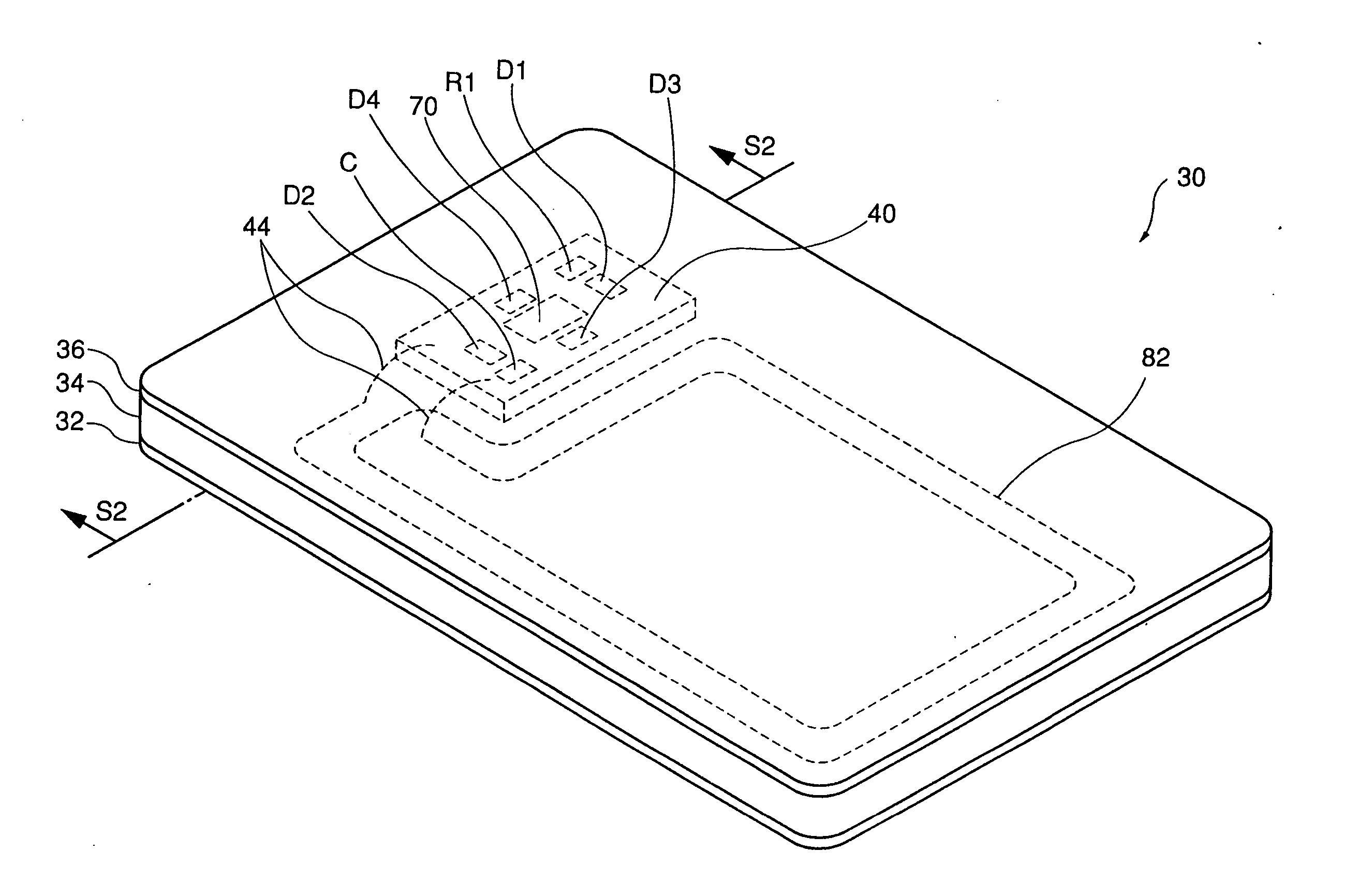
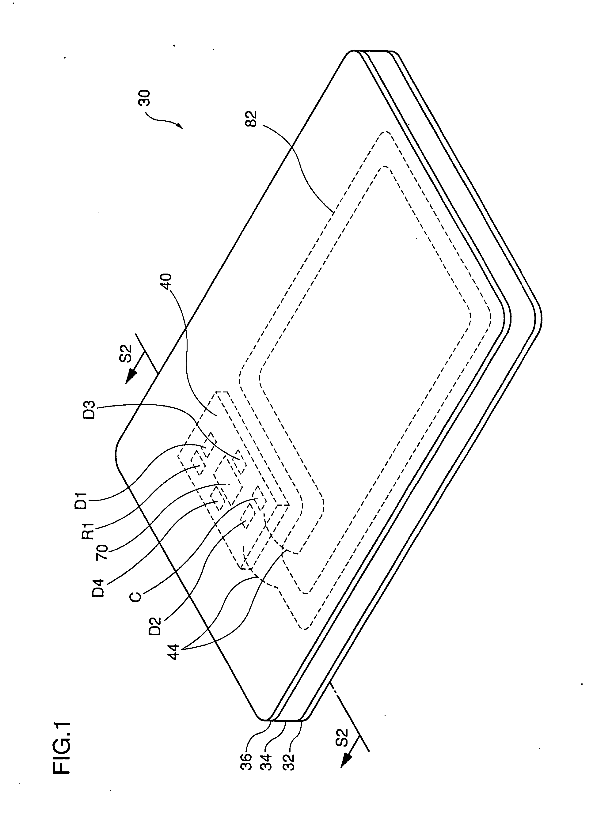
[0062]FIG. 1 shows a configuration of an IC card 30 in a first embodiment of the present invention. In the figure, IC card 30 is a 1-coil IC card which can be used in conjunction with pre-paid cards, automatic ticket-gates of ski lifts, railroads and the like, automatic freight-sorting, and the like.

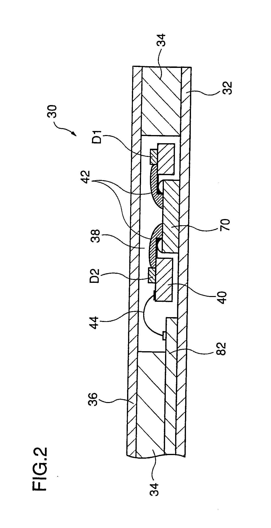
[0063]FIG. 2 is a main cross section of the FIG. 1 IC card 30 (taken along line S2-S2). IC card 30 has a surface member 32, a core member 34 and a surface member 36 that are stacked successively. Surface members 32, 36 are formed of synthetic resin, such as vinyl chloride, polyethylene terephthalate, (PET). Core member 34 is formed of synthetic resin. Surface members 32, 36 and core member 34 define a housing body.

[0064] A cavity 38 is provided in a layer formed by core member 34. In cavity 38 are arranged an IC chip 70, a tape automated bonding (tab) 40 with a mounted capacitor C configuring a resonator circuit 80 (shown in FIG. 3), and other components. Tab 40 is fixed to surface mem...

second embodiment

[0115]FIG. 10A is an exploded perspective view of an IC chip module 92 in a second embodiment of the present invention. IC chip module 92 is incorporated in an IC card used for pre-paid cards, automatic ticket-gates for ski lifts, railroads and the like, automatic freight-sorting, and the like.

[0116] IC chip module 92 is formed by bonding IC chips 86 and 88 to an anisotropic conductor 90. In the present embodiment, a CPU, a modulator / demodulator circuit, a power supply generator circuit and other main circuits (not shown) are mounted to IC chip 86, and a non-volatile memory (not shown) is mounted to IC chip 88. IC chip 86 has an upper surface provided with a plurality of terminals 86a, 86b, . . . , and IC chip 88 has a lower surface provided with terminals 88a, 88b, . . . positionally opposite to terminals 86a, 86b . . . .

[0117] Anisotropic conductor 90 is an adhesive conductor which is conductive only in one direction. It may be, for example, anisolum (available from Hitachi Chem...

third embodiment

[0125]FIG. 11A is an exploded perspective view of an IC chip module 98 in a third embodiment of the present invention. IC chip module 98 includes an IC chip 94 and a seal member 96 stuck on an upper surface of IC chip 94. The present embodiment differs from IC chip module 92 (shown in FIG. 10A) described above in that a CPU, a modulator / demodulator circuit, a power supply generator circuit and other main circuits, and a non-volatile memory are mounted to a single IC chip 94.

[0126] IC chip 94 has an upper surface provided with two terminals 94a and 94b and a pad 95 used to check a non-volatile memory. Seal member 96 is stuck to cover terminals 94a and 94b and pad 95. Seal member 96 on its adhesive side at at least that portion in a strip facing terminals 94a and 94b, provides a strip of interconnection 97 formed of a conductive material.

[0127]FIG. 11B is a circuit diagram of exposure sensor 84 of IC chip module 98. The circuit of exposure sensor 84 of the present embodiment is simi...


PUM


Abstract

In an IC card 30 is sealed an IC chip 70 provided with an exposure sensor 84. When exposure sensor 84 detects that IC card 30 has been opened, exposure sensor 84 outputs an exposure detection signal to a CPU 76. In response to the exposure detection signal, CPU 76 provides a predetermined operation, such as erasure of data in a non-volatile memory 78. As such, the data in non-volatile memory 78 cannot be obtained if IC card 30 is improperly opened to check the data in non-volatile memory 78. Thus the IC card can obtain an enhanced data security.

Description

TECHNICAL FIELD [0001] The present invention relates to IC cards and IC chip modules and in particular to IC cards and IC chip modules with enhanced security. BACKGROUND ART [0002] A communication system employing a non-contact IC card is used for automatic ticket-gates of ski lifts, railroads and the like, automatic freight-sorting, and the like. FIG. 15 is a perspective view showing one example of a conventional non-contact IC card. An IC card 2 shown in FIG. 15 is a 1-coil IC card comprised of a coil 4 used as an antenna, capacitors C1 and C2, and an IC chip 8. [0003] Capacitors C1, C2 and IC chip 8 are mounted to a synthetic resin substrate in the form of a film. The substrate with capacitors C1, C2 and IC chip 8 mounted thereto is referred to as a tape automated bonding (tab) 10. [0004]FIG. 16A is a cross section of the FIG. 15 IC card 2 taken along line S1-S1. In the figure, a core member 12 of synthetic resin is sandwiched by paired surface members 14 and 16. Tab 10 with capa...

Claims


Application Information

Patent Timeline
Patent Type & Authority Applications(United States)
IPC IPC(8): G06F12/14G06F1/00G06F21/75G06F21/86G06K17/00G06K19/06G06K19/07G06K19/073G06K19/077G07F7/10
CPCG06F21/86H01L2924/01322G06K19/073G06K19/07372G06Q20/341G06Q20/382G07F7/082G07F7/1008H01L2224/48091H01L2924/19041H01L2924/3011H01L2924/3025G06F2221/2143H01L2924/01055H01L2924/00014
Inventor IKEFUJI, YOSHIHIROOKADA, HIROHARU
Owner ROHM CO LTD
Why Eureka
Try Eureka